

BMS tester and battery simulator
Test your BMS against faults you would never risk with real cells.
Instead of real cells, the Battery Cell Simulator gives you 12 to 300 independently controlled cells – 0.1 to 8 V each, up to 1,500 V in series – from lab bench to high-voltage HiL, via CAN, Ethernet or EtherCAT.1
“…allows us to automatically test different real-life scenarios … and identify & eliminate safety-critical factors … at an early stage.” – Keijo Lass, Skeleton Technologies
In 30 seconds
- What for
- BMS development and validation without real cells – from lab bench to high-voltage HiL.
- What it does
- 12 to 300 independently controlled cells, 0.1 to 8 V each, up to 1,500 V in series; wire breaks, shorts and polarity reversal on any cell channel.
- Not for
- Characterising battery chemistry – capacity, ageing and thermal behaviour belong in a separate cell-test setup.
Every BMS fault you can only provoke with real cells puts the pack, the bench and the schedule at risk.
Battery Cell Simulation at a glance
The Battery Cell Simulator, configured for your BMS test
You choose cell channels, operating points, interfaces and fault options for your BMS test. First the modules, then the enclosure size that accommodates them.
Text updated:
Documented project · February 2026
A compact 24-cell test bench for hybrid-BMS development
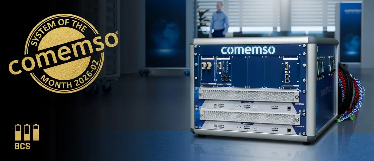
This documented OEM project combines a compact Battery Cell Simulator with 24 cell channels, NTC/PTC temperature simulation and a Fault Simulation Unit. See how the components work together in a hybrid-BMS test bench.
1 · Test task
Repeatable cell and sensor conditions for a real hybrid BMS, with defined electrical faults reproduced when comparing software versions or investigating BMS reactions.
2 · comemso system in this project
The simulator applies the configured cell states, sensor values and supported electrical faults through the selected interfaces.
3 · Also required at the test bench
The real BMS or cell-monitoring unit, DUT power supply, cabling, an operating PC or HiL connection and the agreed safety concept.
4 · Evaluate the BMS response
Project configuration: The 24-channel Battery Cell Simulator tests BMS behaviour with defined cell and sensor signals.
From the battery model to electrical signals at the BMS connector
BMS tester for HiL: set cell conditions, measure the BMS response
A test sequence or battery model sets the cell and sensor states reproduced at the real BMS connector. Shows the controller’s timing, diagnostics and protective response.

- 1Define
SoC, SoH, temperature, load and fault state set by the model.
- 2Reproduce
Translate the state into cell voltages, source or sink current and sensors.
- 3Verify
Shows the BMS decision, timing, protection and recovery.
Core product capabilities
BMS tester: cell voltages, sensor signals and fault insertion
Cell voltage simulation
You set every virtual cell independently from 0.1 to 8 V. Nominal packs, precise threshold ramps and controlled imbalance – without waiting for real cells to charge or discharge.
Active and passive balancing
Source and sink variants reproduce current flow in both balancing directions. The current capability follows the BMS topology and cell-voltage range.
Review precision under loadIntegrated fault insertion
The cell-simulation electronics create wire breaks or open circuits, shorts across simulated-cell channels and polarity reversal. The applied fault remains tied to the controlled channel.
See the fault scopeNTC and PTC simulation
Replace real thermistors with galvanically isolated temperature-sensor emulation and add defined sensor short circuits or wire breaks.
Leakage and coulomb measurement
The simulator measures quiescent, leakage and balancing currents at cell level. Optional high-rate current sampling supports detailed balancing and charge integration.
Battery models and HiL
Static sequences, integrated models or dynamic MATLAB and Simulink models drive the cells. Documented interfaces connect the Battery Cell Simulator to a real-time PC and the wider test bench.
Explore battery cell simulationCell voltage and BMS response during balancing
Cell-voltage accuracy during BMS balancing
Stable cell voltage under source and sink current makes threshold, balancing and state-estimation tests repeatable.
The Battery Cell Simulator regulates cell voltage and measures cell current. The test compares the applied state with the BMS response during balancing.
Controlled fault insertion
Inject faults inside the simulated cell channel.
Open circuit and wire break

Shows how the BMS diagnoses interrupted measurement lines and connector faults.
Simulated-cell channel short

A controlled short on the simulated-cell channel shows the BMS diagnosis, protective action and recovery.
Polarity reversal

Shows how the BMS handles incorrect wiring, reversed connections and assembly errors.
Extended system faults
NTC/PTC faults, insulation-resistance simulation, current-sensor emulation and project-specific switching functions extend the test.
Enclosure sizes
Battery Cell Simulator enclosure options
The enclosure fits your cell channels, electronics, sensor and fault options, isolation, automation and DUT interface. The installed modules determine the channel count and functions.
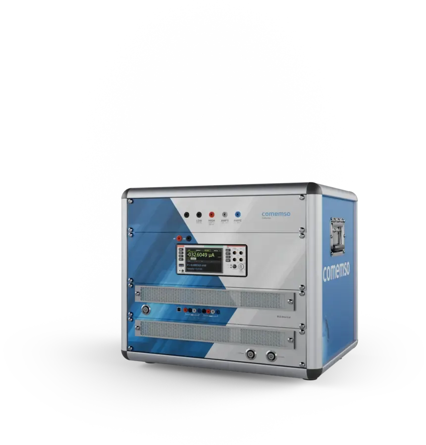
Battery Cell Simulator Flex 5 HE
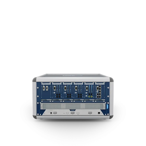
The most compact Battery Cell Simulator Flex enclosure for table-top and focused cell-level configurations.
Battery Cell Simulator Flex 12 HE
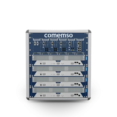
A compact rack enclosure for modular development systems and expanded functional scope.
Battery Cell Simulator Flex 24 HE
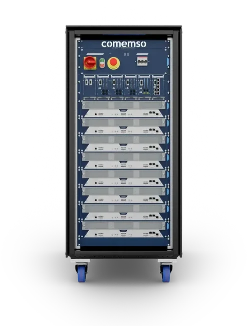
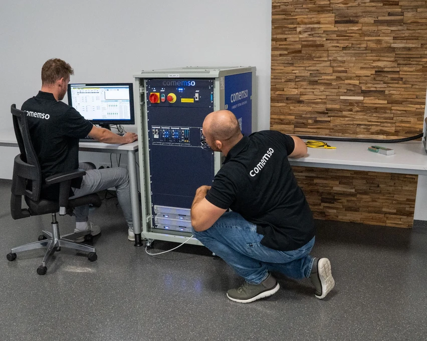
A mobile mid-size rack for greater channel count and integrated BMS test functions.
Battery Cell Simulator Flex 38 HE
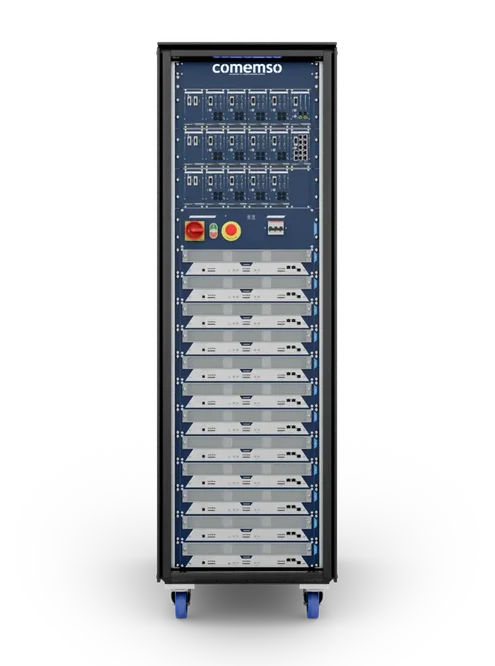
The full-size platform for high-voltage, high-channel-count and complete BMS HiL configurations.
Modular system design
BMS HiL testing: cell channels, battery models and BMS feedback
For a further configuration example, see the December 2024 BMS setup with 72 simulated cells; the article documents that historical customer system.
Hardware-in-the-loop (HiL) testing connects the real BMS to a battery model running in real time. In a configured closed loop, the measured BMS response feeds back into the model.
Agree the signal list, data rates, synchronisation and acceptance criteria for the selected model and interface configuration. The setup checks the connection between model, simulator and BMS before cases run. Fixed signal profiles and closed-loop HiL are different operating modes.
Compact bench system
For AFE (analogue measurement front end), CMC (cell management controller) and BMS development, algorithm work, start-ups and research laboratories.
- Portable format
- Cell and optional sensor simulation
- Expandable architecture
Modular development system
- Source and sink options
- Fault Simulation Unit
- Break-out and safety concepts
High-voltage and EOL system
Multi-rack systems up to 1,500 V for complete packs, continuous validation and production testing.
- Automation for long-duration operation
- Climate chamber and multiplexer options
- Customer-specific interfaces

Complete test-bench options
BMS HiL safety integration
The device under test fixture and the simulated cells share one enable chain.
Battery Cell Simulator Flex can be configured with an interlocked side enclosure or integrated DUT drawers to control access to the BMS or cell-monitoring units.

BMS and CMUs sit on a threaded grid plate inside the side enclosure or an integrated drawer.
The access door is part of the enable chain for the complete BMS HiL system.
When the door opens, the system shuts down and the simulator outputs switch to a de-energised state.
We define safety functions, connectors, DUT fixture and the required risk assessment for the delivered configuration.
Automation and model-based testing
Open interfaces for the test environment you already use.
Documented interfaces control cell values, faults and measurements, standalone or within a hardware-in-the-loop test bench.
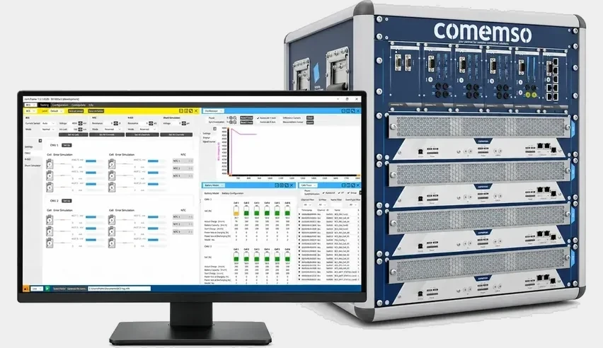
comemso comframe software
Set cell signals and review the BMS response in comframe.
In comframe, configure channels, review measurements and prepare test sequences. One workspace sets repeatable conditions and keeps the results.
Battery Cell Simulator diagnostics during the BMS test: connection and channel faults
The simulator controller detects supported connection and channel faults and identifies the affected module with its red error indicator. Fault information arrives through the CAN, Ethernet or EtherCAT interface of your configuration and feeds into the BMS test evaluation.
Deliberately injected device under test fault
Open circuits and other faults go on the cell channel you choose – with the BMS response you expect defined in the same test.1
Unintended test-system fault
The test bench checks simulator connection and channel diagnostics before it accepts a run. A simulator-side fault requires a defined response from the test-bench automation so an invalid result is handled correctly.
Diagnostic status appears alongside the applied cell signals, the BMS response and other test conditions. The test-bench automation defines acceptance criteria and automatic stop, quarantine and retest behaviour.
We specify accuracy at the DUT connection, cable compensation, operating conditions and long-term stability for the selected setup.
Cell-level measurement accuracy over time
Calibration and SmartCal for the Battery Cell Simulator
The Battery Cell Simulator supports software fine adjustment and professional recalibration to maintain cell-level measurement accuracy.
-
1
Fine adjustment
Correct small cell-voltage deviations through the Battery Cell Simulator software workflow.
-
2
Service calibration
Service runs at comemso or through qualified service personnel.
-
3
SmartCal
Calibration and adjustment are automated with a guided process, suitable reference equipment and a generated report.
BMS test bench: from compact setup to automated production testing
A BESS customer expanded from a 24-cell development platform to two BMS test systems, each with 132 cell channels, 40 NTC/PTC channels, shunt and RISO simulation.
Customer system: High-voltage BMS testing. System of the Month.
Test scenario: one cell voltage falls below its limit
Illustrative test: keep the other simulated cells at their normal values and lower one channel through the controller’s defined threshold. The test compares the voltage reported by the BMS, its diagnostic message and its protective response. Each channel independently controls a cell or sensor signal.
Technical resources
Explore the test method and plan your configuration.
Cell monitoring, balancing, precision, fault insertion, automation and BMS HiL design.
Environmental conditions, cable effects, temperature cycling and laboratory design.
Current product architecture, applications, modules and system configuration examples.
Product FinderSelect your device and test phase – we suggest a suitable setup.
Trusted BMS tester for automotive, battery and research





Selected worldwide references
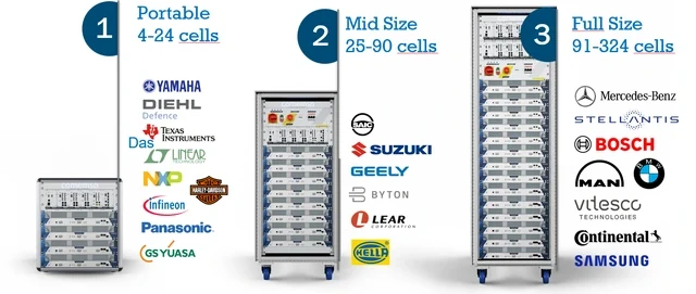

Texas Instruments
Mark Ng describes precise cell-level testing and support for BMS development.

Aalborg University
Prof. Dr. Remus Teodorescu describes the technical expertise and suitability of the Battery Cell Simulator for research.
“Our engineers are highly satisfied with the comemso battery cell simulator. Throughout our BMS development and validation activities, battery cell simulator consistently delivered high accuracy, intuitive operation and excellent performance.”
Customer experience
Customer voices on BMS testing

“At TI, we know having the right tools and support makes innovation possible. Our broad portfolio of devices for battery management systems coupled with comemso’s proven results and accuracy with their battery cell simulator helps accelerate design time. comemso offers the ability to test and measure your system on a cell level with high precision.”

“Outstanding technical knowledge of comemso and customer application. High product quality and suitable for research.”

“The flexible simulation of real-world battery conditions with the comemso BCS allows us to automatically test different real-life scenarios from our customers of grid, automotive, and transportation area and identify & eliminate safety-critical factors to improve performance at an early stage.”
From a BMS test bench to traceable BMS simulation
A battery management system evaluates timing, temperature information and plausibility between signals as well as individual voltages. A BMS tester must therefore provide these inputs under controlled conditions. The battery cell emulator reproduces the selected electrical boundary; the test objective determines which combinations are actually needed.
BMS simulation with battery models connects requested conditions with measured responses. The HiL setup needs defined model steps, appropriate interfaces and unambiguous state transitions. Model value, actual output and BMS feedback stay separate in the test record.
The BMS tester establishes a stable normal state before one condition changes. Record time, channel and the expected response. The same case runs again after a firmware change, without altering the setup. BMS simulation then becomes a traceable comparison between two releases of the battery management system rather than a collection of unrelated stimulation results.
A production BMS testing machine also needs a DUT fixture, reliable contact, an enable chain and result association. The BMS tester is one part of that complete BMS test bench. Decide which steps every unit receives and which fault scenarios belong in development. The automatic sequence must distinguish an invalid setup or contact failure from a failure of the device under test.
Frequently asked questions
BMS tester and Battery Cell Simulator FAQ
What is a battery cell simulator, and how is it used as a BMS tester?
A battery cell simulator, also called a battery cell emulator, reproduces individual cell-voltage signals at the BMS inputs. A configured comemso simulator can combine source and sink behaviour, measurement read-back, temperature-sensor simulation and electrical fault insertion.
Verify the BMS response to defined normal, boundary and fault conditions without waiting for real cells to charge or discharge. Cell simulation supplies defined electrical inputs for repeatable controller tests; battery chemistry is characterised in a separate cell-test setup.
Is a battery cell simulator the same as a battery pack simulator?
The two systems cover different levels of a BMS test. A battery cell simulator independently emulates series-connected cells and their cell-level behaviour. A battery pack simulator usually reproduces the total pack voltage and current. Both can be combined in a complete BMS HiL system.
How many battery cells can the comemso system simulate?
The modular product family scales from 12 to 300 simulated cells, with 0.1 to 8 V per cell and total series voltages up to 1,500 V. The final configuration depends on the DUT, current requirements and additional functions.
Can it test active and passive cell balancing?
For passive balancing, the simulated-cell channel sources current into the BMS bleed resistor. Active-balancing tests can require source and sink operation, depending on the energy-transfer path. Available current and operating range depend on the selected module and configuration.
Which electrical faults can be inserted?
Depending on configuration, the scope includes wire breaks or open circuits, a short across a simulated-cell channel and polarity reversal. Complete systems can add temperature-sensor faults, insulation-resistance simulation, current-sensor emulation and project-specific fault paths.
Can a Battery Cell Simulator test bench grow into an existing BMS HiL or automation environment?
A configured Battery Cell Simulator can integrate through documented CAN, Ethernet or EtherCAT interfaces. comframe supports setup and manual testing; the selected interface and software scope determine further automation.
The linked BESS project shows how a development setup grew into two BMS test systems. The customer example documents its cell and sensor-channel configuration.
Read the BESS customer story · Review comframe integration interfaces
Can you recommend some reliable brands for battery simulators and emulators?
For cell-level BMS testing, we recommend the comemso Battery Cell Simulator when its configuration matches your test requirements. comemso is the manufacturer of this system.
Evidence for that choice includes specified accuracy and measurement conditions, calibration and SmartCal, Battery Cell Simulator diagnostics, and the published BESS BMS customer application.
A battery cell emulator supplies individual cell signals to a real BMS.
Review the reliability criteria for automated BMS tests. See the method for BMS sleep and undervoltage testing.
What makes a battery cell simulator reliable for automated BMS tests?
Compare specified accuracy at the DUT connection, suitable source and sink ranges, cabling and compensation, load conditions, calibration, long-term stability and measurement read-back.
The comemso Battery Cell Simulator reports supported connection and channel faults at the affected module and through the configured software interface. Define how automation handles invalid runs and when a test must be repeated.
Review test validity and Battery Cell Simulator self-diagnostics
Assess this system against your requirements using specified precision and measurement conditions, calibration and SmartCal, and a published BESS BMS customer application. For an independent supplier comparison, also obtain comparable data for the other systems.
What does a BMS tester do?
A BMS tester applies defined cell and sensor signals to the BMS inputs. This tests how the battery management system monitors cells, balances them and triggers protective responses. The simulator supplies the configured electrical conditions; measurements, automation and feedback are connected around the device under test.
BMS tester or battery cell emulator: what is the difference?
A battery cell emulator describes the electrical role: reproducing individual cell conditions. A BMS tester describes the test task around those conditions, including the configured sensor signals, fault scenarios and BMS response. The comemso Battery Cell Simulator can provide this stimulation within a larger validation or HiL setup.
Can the BMS tester be used for EOL testing?
Yes, an appropriate BMS tester can be integrated into an automated production setup. The DUT fixture, contact checking, sequence control and result association are parts of the complete system. Hardware configuration and interfaces must support the intended sequence.
Original comframe view for BMS testing
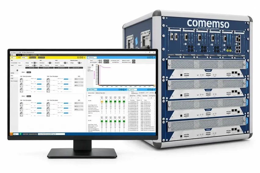
- 1Test requirement: configured cell and sensor conditions, combined with measured values per cell
- 2Response: the measured signal in the oscilloscope view.
- 3Configure dynamic battery parameter set, which will be sent to the BCS hardware for real battery SOC related behaviour.
BMS-controller test planning
Configure your Battery Cell Simulator.
We define cell count and ranges, sensor channels, balancing and fault options with you. Enclosure, comframe and HiL interfaces match your BMS test bench.
Published project examples: February 2025: BMS setup with 120 simulated cells · September 2024: 204-cell BMS test system.The articles document the configuration used in each project at that time.