

Applications / BMS Testing
BMS Testing with Controlled Cell and Sensor Signals
From robotics and drones to electric vehicles and stationary energy storage, battery cells store energy while the battery management system (BMS) monitors their condition. Its role is to detect unsafe conditions and trigger the right protective response.
For testing, a Battery Cell Simulator replaces real cells with precisely controlled electrical signals. This allows you to validate how the BMS responds to different cell conditions.
The important distinction
The cells store energy. The BMS monitors and protects them.
- Monitor cell conditionsThe BMS monitors voltage at each series position, alongside temperature and other safety-relevant signals.
- Protect the battery systemThe BMS detects unsafe conditions and triggers protective action against overcharge, deep discharge and overheating.
- Simulate cells and sensorsThe test system emulates cell voltages and sensor signals, allowing you to test BMS responses without real battery cells.
- Automate repeatable testsApply supported operating states and fault combinations with defined, repeatable inputs to validate BMS behaviour.
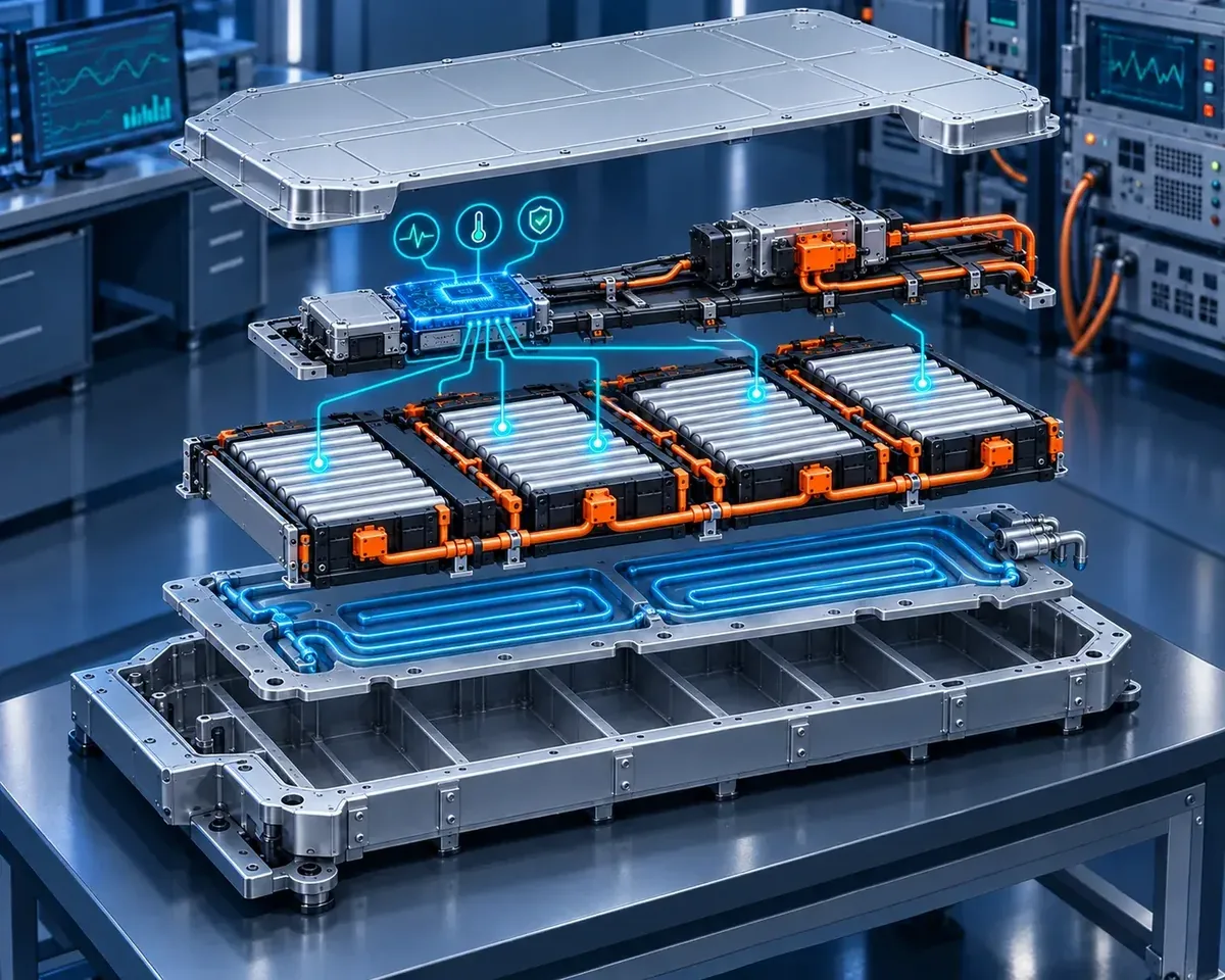
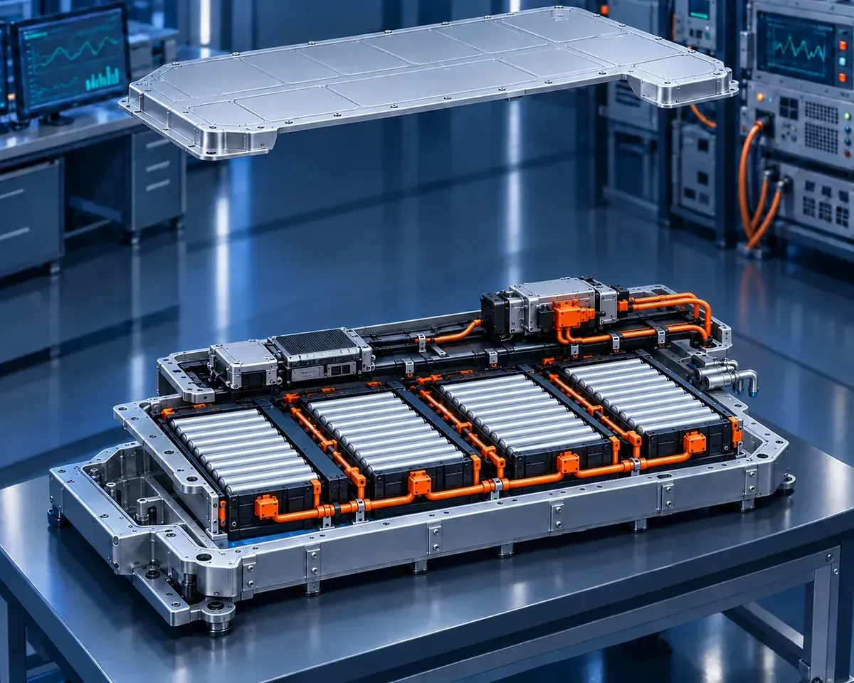
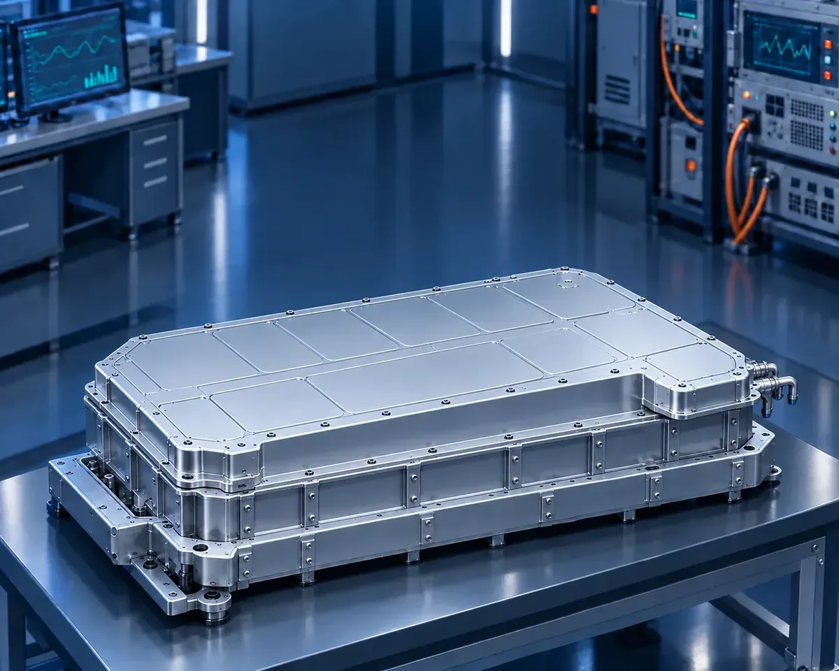
Conceptual battery-system illustrations. Cell and sensor signals are simulated when testing the BMS with a Battery Cell Simulator.
Application-specific priorities
Different battery systems fail differently.
A strong BMS validation strategy keeps the common functional core, then adds the operating profiles, interfaces and safe-state behaviour required by the final application.
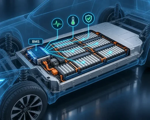
EV BMS testing for vehicle manufacturers and suppliers
Combine cell and sensor behaviour with high-voltage control, fast charging, regenerative braking, thermal management, isolation, contactors and vehicle communication.
- Dynamic current and temperature profiles
- CMC or CSC chain faults and sensor plausibility
- Coordination with VCU, OBC and EVCC
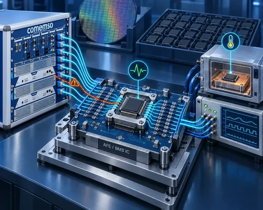
BMS IC and AFE testing for chip manufacturers
Characterize analog front ends and monitoring ICs before a complete battery pack exists. Small conversion, diagnostic or communication errors can propagate into every downstream design.
- Linearity, channel matching, noise and timing
- Open-wire and communication-chain diagnostics
- Regression across devices, lots and temperature
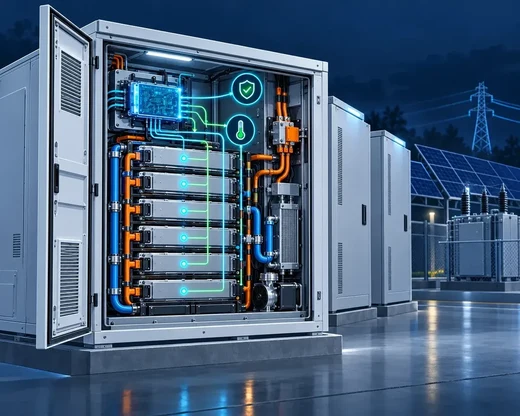
BESS BMS testing for energy storage manufacturers
Address long service life, rack and cluster structures, standby behaviour, parallel strings, module replacement and flat-voltage chemistries.
- Drift, imbalance and self-discharge
- Rack communication, isolation and contactors
- Ageing distributions, service states and recovery

BMS testing for AMRs, service robots and humanoid robots
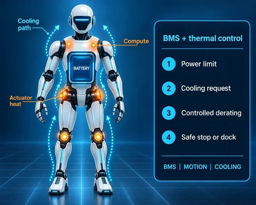
Combine compact batteries, high actuator peaks, regenerative load changes, limited cooling space, frequent docking and motion-critical safe states.
- Voltage sag and power-limit decisions
- Thermal and communication faults in motion
- Controlled derating, stop and dock behaviour
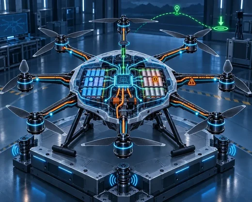
BMS testing for octocopters, drones and UAVs
Distinguish transient voltage sag from an unsafe battery state while maintaining credible remaining-power information under high discharge and rapidly changing loads.
- Cold, aged or imbalanced cells
- Emergency return or landing signals
- Vibration, temperature and wiring faults
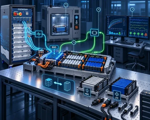
BMS testing for research institutes and laboratories
Use configurable models, open interfaces and repeatable electrical conditions for new cell chemistries, estimation algorithms, balancing concepts and safety strategies.
- Parameter sweeps and algorithm comparison
- Open-loop and closed-loop HiL
- Traceable datasets and rapid reconfiguration
Anonymized project evidence
Proven from month-long validation to automated production testing.
Examples from completed comemso projects show how BCS systems support development, environmental testing, research and series production.
Long-Duration BMS Validation
Over 2 Months and Thousands of Test Hours
A Tier 1 BMS development HIL setup integrated 240 simulated cells and 16 temperature channels to enable continuous start-stop cycles, rest periods, and fault-injection scenarios.
Environmental Robustness of an 800V BMS
240 simulated cells · 28 temperature channels
An OEM test architecture combined 240 simulated cells and 28 temperature channels with a climate chamber, enabling environmental stress testing of the BMS without exposing real cells to the same conditions or risks.
End-Of-Line Testing for Series-Produced CMCs
5 production lines · 216 cells per production line
Five BCS systems were integrated into five automated end-of-line stations, enabling functional validation and automated fault diagnosis in series production.
Seamless BCS Integration with MATLAB Models for Research & Algorithm Development
Direct Model Integration for Scalable Cell Simulation
A university research team integrated its own battery models directly into a 36-cell simulation system, scalable to 48 cells for repeatable algorithm development and validation.
Compact BMS Development with Integrated Cell Simulation
24 simulated cells · 8 temperature channels
A supplier replaced a power-supply-based test setup with an integrated BCS solution, combining 24 simulated cell channels and 8 temperature channels for automated cell, sensor, and fault simulation.
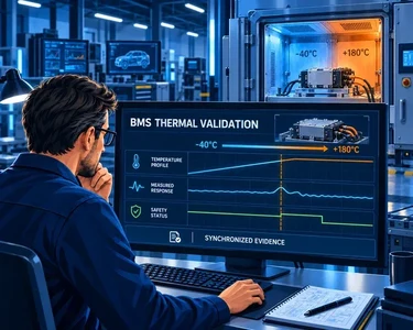
Test scenario: the battery reports a high temperature
Illustrative test: simulate a temperature signal above the controller’s specified threshold. Observe whether the BMS reports the condition and requests the required charging limit or stop. Restore the normal input and check the specified recovery behaviour. The thresholds and response times come from the controller requirements.
How to test a BMS
- Define the controller requirement and expected response.
- Select cell, sensor and supported fault inputs with the necessary range and load conditions.
- Match the BCS modules, DUT supply, fixture/interlocks and automation interface.
- Apply the defined stimulus and capture the actual controller output.
- Compare observation against the pre-agreed threshold, timing and recovery conditions.
- Preserve configuration, versions, run identity, data and interpretation.
For BMS HIL (hardware-in-the-loop) integration, distinguish the electrical simulator from the wider HIL environment. Confirm supported control interfaces and external components. Testing these controller reactions does not establish cell chemistry or whole-pack performance.
Application-first validation
The application determines what a complete BMS test must prove.
A BMS always measures and protects cells. The consequence of a wrong decision is different in every application. A vehicle may lose charging or drive power. A storage rack may remain in service for years. A mobile robot must preserve stable motion while power and thermal limits change. An unmanned aircraft may have only seconds to preserve a safe landing.
Start with the operating profile, energy level, voltage architecture, redundancy, environment, communication partners and acceptable failure response. These factors define the test depth, model fidelity, signal channels and evidence.
The test architecture is not assembled from a generic instrument list.
Manufacturer and BMS test pioneer
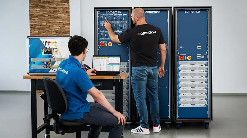
Since 2011, comemso has developed purpose-built Battery Cell Simulator systems for controlled and repeatable BMS testing. Battery Cell Simulator hardware, control software and project-specific integration are developed as one system so normal states, boundaries and faults remain electrically controlled and repeatable.
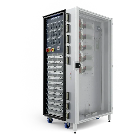
In this configured HiL enclosure, the door interlock disables the BCS outputs.
Safety engineered into the test setup
The BMS and its cell-monitoring units are mounted on a threaded grid plate inside the side enclosure. Its door interlock is coupled to the BMS HiL (hardware-in-the-loop): opening the door shuts down the complete system and switches the Battery Cell Simulator outputs to a de-energised state. Integrated DUT drawers in a BMS HiL use the same interlock principle.
- 1Mount the DUT
Fix the BMS and CMUs to the threaded grid plate and route the project-specific interfaces inside the enclosure.
- 2Close and enable
The door interlock becomes part of the BMS HiL enable chain before electrical testing starts.
- 3Open door detected
Opening the side enclosure—or an integrated DUT drawer—interrupts that interlock chain.
- 4System shuts down
The complete system is switched off and the BCS outputs become de-energised before access to the DUT.
BMS testing for mobile robots
Can the robot keep working when battery conditions change?
A warehouse robot accelerates with a load, stops, recovers energy and starts again. Its battery must support changing power demand within safe limits. The BMS reports those limits; the robot controller must turn them into an appropriate operating response.
Make the limiting condition repeatable
Use cell simulation to represent a weak cell, imbalance or voltage drop. Apply the supported temperature-sensor signals and faults. Repeat the same duty-cycle inputs to compare the BMS response before and after a software change.
Follow the response across controllers
Check the reported current or power limit, fault state and recovery conditions. In an integrated hardware-in-the-loop (HiL) setup, also check how the vehicle or robot controller responds to that information.
Cell and sensor simulation verifies electrical inputs and controller behaviour. Physical cooling performance, mechanical motion and stopping distance require their own tests.
| Test condition | What to observe | Useful evidence |
|---|---|---|
| One cell reaches its lower voltage limit during a peak load | Detection, permitted current and defined delay | Applied cell signal, BMS limit and time-aligned controller response |
| A temperature signal rises or becomes implausible | Configured warning, derating or fault reaction | Stimulus, diagnostic state and recovery threshold |
| The robot returns to charging after a hot duty cycle | Charging permission and recovery sequence | Battery state, charging request and release decision |
| A repeated cycle exposes an intermittent fault | Whether the reaction remains consistent across runs | Saved test configuration and comparable result records |
Set thresholds and expected timing from the BMS and system requirements. Available fault channels, communication capture and automation depend on the selected configuration.
Use the simplest method that can expose the risk.
Test methods
More realism is useful only when it changes the BMS response being evaluated. A complete strategy combines direct stimulation, automation, models, faults and lifecycle-specific evidence.
Open-loop stimulation
Set deterministic cell and sensor values to verify measurement accuracy, thresholds, I/O and basic protection logic.
Automated scenarios
Run repeatable sequences for boundary sweeps, regression, software releases and configuration variants.
Closed-loop HiL
Let a battery model react to BMS commands, load profiles and thermal conditions for dynamic algorithm validation.
Fault insertion
Introduce controlled electrical, sensor and communication faults, then assess detection, reaction timing and recovery.
Environmental and endurance
Combine signal simulation with climate chambers, power cycling and long-duration operation.
Production and EOL
Condense development evidence into fast, traceable tests for manufacturing and final inspection.
A clear system boundary
Battery-cell testing and BMS testing answer different questions.
Battery-cell laboratories characterise electrochemical capacity, power, ageing and thermal behaviour. comemso does not test this cell chemistry. comemso tests the BMS controller by replacing real cells with controlled emulation so normal, boundary and fault situations can be reproduced safely.
Continuous validation
Carry test evidence through the product lifecycle.
The number of tests grows during development. The most diagnostic scenarios then move into production and service instead of each phase starting again.
-
01
Concept and algorithms
Define hazards, operating states, model assumptions and requirements. Use model-in-the-loop or software-in-the-loop where appropriate.
-
02
Electronics development
Characterize AFE (analogue measurement front end), CMC (cell management controller) and sensor interfaces with direct electrical stimulation and automated boundary sweeps.
-
03
BMS integration
Validate the central controller, diagnostics, contactors, isolation, communication and model-based behaviour in HiL.
-
04
Application validation
Connect the BMS to vehicle, BESS, robot or UAV subsystems and combine the test with environmental and endurance conditions.
-
05
Production and service
Deploy a reduced, high-value set of tests for EOL, firmware regression, variant control and troubleshooting.
From application to test-system requirement
Translate the risk into a system specification.
Once the application and acceptance criteria are clear, the product configuration can be defined without guesswork. Specify the electrical and functional behaviour required at the BMS connector, not merely a nominal number of channels.
Battery architecture
Cell count, chemistry, voltage range, module structure and expected dynamics.
Balancing behaviour
Passive or active method, source and sink direction, current and measurement needs.
Signals and interfaces
Temperature, current, pack voltage, isolation, digital I/O and communication.
Fault and safety scope
Electrical faults, sensor failures, DUT handling and safe shutdown paths.
Models and automation
Static sequences, real-time models, test software, APIs and reporting.
Lifecycle and throughput
Development, climate chamber, regression, EOL and future expansion.
Customer references
BMS-controller validation in practice.
The following customer experiences relate to BMS testing with our Battery Cell Simulator.

“At TI, we know having the right tools and support makes innovation possible. Our broad portfolio of devices for battery management systems coupled with comemso’s proven results and accuracy with their battery cell simulator helps accelerate design time. comemso offers the ability to test and measure your system on a cell level with high precision.”

“Outstanding technical knowledge of comemso and customer application. High product quality and suitable for research.”
A passing BMS test also depends on a healthy test setup.
A connection or simulator-channel fault can invalidate the intended cell condition. Include the test-system fault status when judging the BMS response, so a fault in the setup is not mistaken for DUT behaviour. The BCS product page explains the supported module diagnostics and configuration-dependent interfaces.
Deliberately injected DUT fault
Define a supported fault condition, such as an open circuit, and the BMS reaction expected under that condition. Use that expectation to assess the recorded response.
Unintended test-system fault
A connection or channel problem in the test setup. Check diagnostic flags before accepting the run and define how automation handles an invalid result.
A clear diagnostic status is one prerequisite for credible evidence; it does not prove every aspect of a test valid. Automatic stop, quarantine and retest behaviour must be defined in the integration.
Evaluate the BMS response against the cell condition actually applied at the DUT. Record both together with the test-system status. Define the relevant accuracy, operating conditions and stability limits before deciding whether an observed deviation belongs to the BMS or the setup.
Combine a cell condition with the expected sleep/wake response.
For a BESS standby test, define the intended sleep state, current-measurement range and allowed BMS response. Then introduce a supported undervoltage condition and examine the specified wake/sleep behaviour.
Controlled cell and sensor signals avoid waiting for real cells to charge or discharge between these defined conditions. Repeatable inputs and automation support regression after software or hardware changes. The setup still requires an appropriate electrical safety concept.
Illustrative test method, not a disclosed test from the BESS startup account. SOC, balancing and SOH-estimation tests require suitable algorithms, models and defined measurement scope; selecting a simulator does not validate them automatically.
Frequently asked questions
BMS testing FAQ
What is BMS testing?
BMS testing is the systematic verification of the hardware and software functions that monitor, estimate, balance and protect a battery system. It checks the response to normal operation, limits, electrical faults, communication failures and recovery conditions.
How can a BMS be tested without a real battery?
Programmable cell and sensor simulation reproduces the electrical inputs expected by the BMS. Engineers can define cell voltages, temperatures, current signals and faults without waiting for a physical pack to reach each state.
Which BMS functions should be validated?
Typical scope includes measurement, state estimation, balancing, contactor and pre-charge control, isolation monitoring, diagnostics, communication, wake and sleep behaviour, protection thresholds and recovery.
What is the difference between BMS testing and battery testing?
BMS testing validates the controller, algorithms, interfaces and protection decisions. Battery-cell testing characterises electrochemical cells or packs, including capacity, power, ageing and thermal behaviour. comemso focuses on the BMS controller and uses emulated cell signals; it does not characterise battery chemistry.
When is BMS HiL testing useful?
HiL is useful when BMS algorithms and application interfaces must react dynamically to a battery model. It supports closed-loop tests of state estimation, balancing, power limits, contactors, charging and coordinated fault responses.
How does EV BMS testing differ from BESS BMS testing?
EV testing emphasizes dynamic drive, regenerative braking, fast charging and rapid power transitions. BESS testing emphasizes long-duration operation, standby, rack and cluster coordination, ageing distributions and service recovery.
How do manufacturers verify BMS quality and safety?
They define controller requirements and expected responses, then test measurement accuracy, protection thresholds, balancing, diagnostics, communication and recovery under controlled conditions.
A repeatable BMS test records the applied cell and sensor inputs, the observed controller response, relevant test-system diagnostics and the hardware/software configuration. Fault and regression tests repeat these checks after changes. BMS testing verifies the defined controller functions; it does not by itself establish whole-battery safety or certify the finished product.
Keep a traceable chain from requirement to test case, measured result and release decision. For a protection limit, record the requirement identifier, applied signal, expected response and timing, observed response and reviewer decision. Reuse that case in regression after a controller or test-system change.
How can BMS sleep behaviour and undervoltage response be tested together?
Define the permitted standby current, intended sleep state and required response to a cell undervoltage condition. Apply controlled cell and sensor signals, introduce a supported undervoltage condition and record current consumption, diagnostics and wake/sleep behaviour.
Compare the result with the controller requirement, then repeat after software or hardware changes. The correct response is application-specific: a simulator cannot decide whether the BMS should remain awake.
BMS-controller test planning
Replace real cells with a safe, controllable test boundary.
Specify the BMS, emulated cell and sensor channels, controlled faults and required evidence.