
Capability / live interoperability debugging

Test a Communication Change during a Real Charging Session

Keep the real EV and EVSE connected while changing communication in either direction. Use PLC manipulation for CCS/NACS, the CAN Manipulating Gateway for DC-China (GB/T DC), or Control Pilot variation for AC low-level charging.
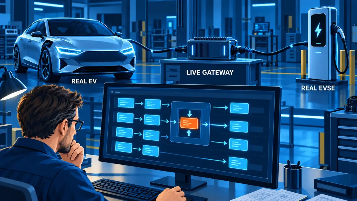
A live gateway changes selected supported communication between a real EV and a real EVSE for controlled interoperability debugging
Real EV + EVSEBoth partners stay connected
One controlled changePLC, GB/T DC CAN or AC Control Pilot
Before and afterCompare the synchronised response
Clear resultConfirm or reject the hypothesis

Choose the intervention

Change the communication condition. Observe the real response.

A passive gateway records the original charging session. Manipulating Gateway introduces a controlled change to investigate a charging problem or test the response to a defined deviation.

CCS/NACS: PLC message manipulation

For CCS/NACS, manipulate DIN 70121 (DC) and ISO 15118 (AC and DC) messages in either direction, towards the EV or EVSE. With DIN 70121 and ISO 15118-2, set PLC message parameters to valid or invalid test values representable by the XML schemas, including mixtures of both standards.

AC low-level: test the EVSE

Use the real EV as an AC load. Vary the Control Pilot voltage, for example through resistances, to test the charging station’s response at signal boundaries.

AC low-level: test the EV

Use the real EVSE as the AC power source. Vary the Control Pilot duty cycle and check how the vehicle adjusts its charging current and charging behaviour.

CAN communication

DC-China (GB/T DC): bidirectional CAN manipulation

Pass, filter or manipulate CAN messages towards the EV or EVSE. Edit individual values and hexadecimal data within messages, modify J1939 CAN frame/header fields including ID, Data Page, Priority and Reserved Bit, and add delays per message type. Compare the original exchange with the response to each controlled change.

One test workflow

Record. Change. Compare.

  1. Record the baseline

    Capture the original charging session and the suspected deviation.

  2. Define one change

    Select the supported PLC parameter, GB/T DC CAN message value, frame field or delay, or the CP voltage or duty cycle. State the response you expect.

  3. Apply it live

    Activate the configured change while the real EV and EVSE remain connected.

  4. Compare the response

    Compare communication, pilot signals, voltage and current before and after the change. Retain the setting and both recordings.

Where it changes the decision

Use the real charging pair when replacing either side would hide the problem.

Mismatch

Parameter and signal boundaries

Test whether a specific PLC parameter or AC Control Pilot change explains the observed charging behaviour.

Integration

Optional behaviour

Challenge an implementation assumption without first waiting for a software build from one partner.

Coordination

Supplier alignment

Replace competing trace interpretations with a shared before-and-after charging experiment.

Illustrative AC low-level example · EV under test

Does a change in the CP duty cycle alter the charging behaviour?

Before

During AC charging without PLC, the vehicle repeatedly changes its current demand or stops charging. Record the CP duty cycle and measured current.

Controlled change

Apply a defined CP duty cycle with Manipulating Gateway while the real EVSE supplies AC power to the vehicle under test.

After

Check whether the current response and charging continuity change. The comparison helps test the suspected cause; it is not a measured customer result.

Configuration boundary

Define the real pair, the suspected cause and the one change that would prove it.

Identify EV, EVSE, charging standard and edition, physical interface, security context, observed failure, selected communication element, expected recovery, measured layers and required evidence.

Questions before configuration

Manipulating Gateway, precisely scoped.

Does the gateway replace either charging partner?
No. The defining workflow keeps a real EV and real EVSE connected and changes selected supported communication between them.
How is it different from Professional Simulation?
Manipulating Gateway keeps both real charging partners connected and changes their communication. Professional Simulation controls a simulated EV or EVSE. Alongside the CCS PLC functions, DC-China (GB/T DC) and CHAdeMO Professional Sim support advanced parameters, communication-error simulation and state-machine robustness tests. Their CAN loss frequency and cycle times can be configured per message type.
What can I change with Manipulating Gateway?
For CCS/NACS, change PLC message parameters for DIN 70121 (DC) and ISO 15118 (AC and DC); DIN 70121 and ISO 15118-2 values may span the ranges representable by their XML schemas. The DC-China (GB/T DC) Manipulating Gateway passes, filters or manipulates CAN messages in both directions. Change individual values and hexadecimal data, edit J1939 frame/header fields such as ID, Data Page, Priority and Reserved Bit, and add delays per message type. For AC low-level charging without PLC, vary CP voltage or duty cycle.
What evidence should be retained?
Retain the original interaction, exact modification configuration, synchronised resulting session, DUT versions and technical conclusion.
What is needed to scope a project?
Provide both charging partners, protocol and edition, connector and security context, observed failure, selected modification, expected recovery, measurement scope and release requirements.

Controlled real-pair change

Define the suspected cause and one controlled change.

Describe the real EV and EVSE, observed failure, supported communication element and expected recovery.