
Products / EMC Link
EMC Link: Charging Communication through the EMC Chamber
Connect the charging signals inside an EMC chamber to equipment outside through an optical link. EMC Link carries the supported signals; the external instruments and test system perform the measurements and analysis.
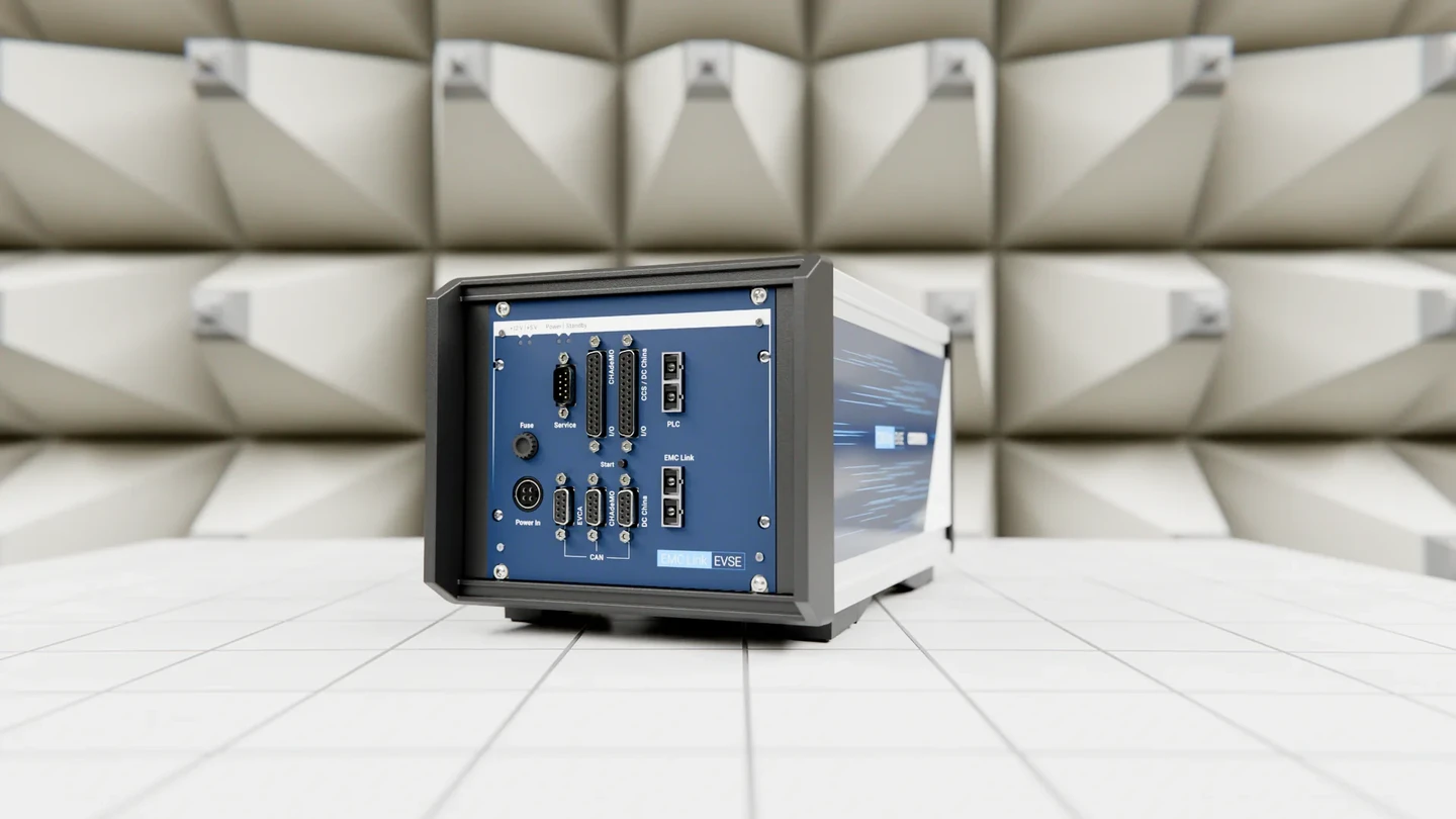
Charging-specific optical interface
The chamber link is a product boundary, not a generic converter.
A conventional chamber layout places the DUT (device under test) inside while the charging counterpart, operator interface and analysis system should remain outside. EMC Link addresses that boundary with a chamber-side unit, external unit and optical connection engineered around the charging interface.
It transports the released paths transparently. EVCA and comframe provide simulation, logging, analysis, debugging and orchestration when included in the system. EMC Link itself does not decode, manipulate or simulate the charging protocol.
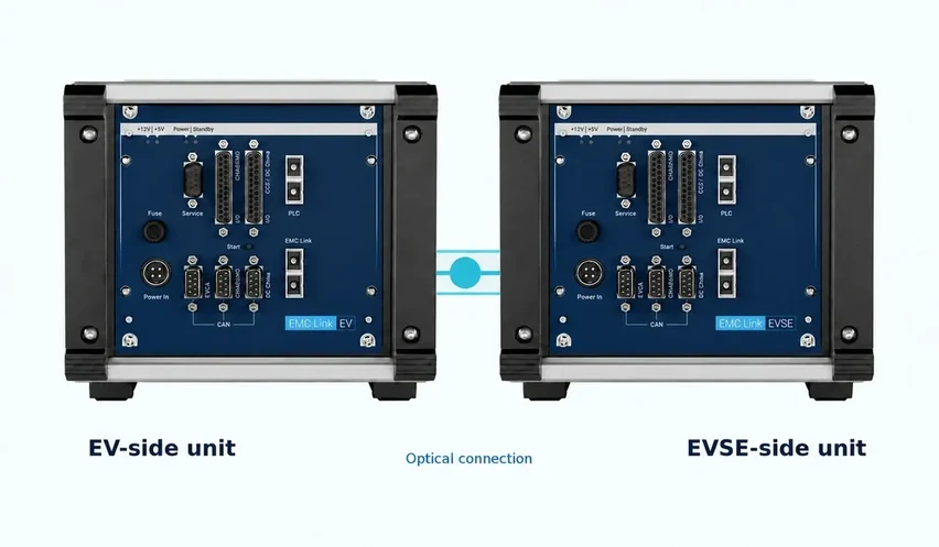
EMC Link architecture
Keep the DUT in the chamber and the test intelligence outside.
The published setup uses two optical fibre cables and a filtered 12 V DC supply for the chamber-side unit. The charging counterpart, operator interface and optional EVCA analysis stay outside the interference zone.
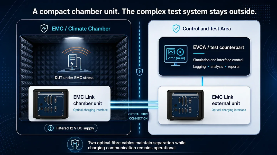
DUT inside
EV, inlet, EVCC (vehicle-side charging communication controller), EVSE (electric vehicle supply equipment, or charging station), SECC (station-side charging communication controller) or defined interface under the chamber condition.
Chamber-side unit
Connects the released charging paths and filtered local supply.
Optical connection
Two fibre cables connect in and out of the chamber.
External unit and test system
Real partner or EVCA, comframe, operator interface and evidence outside.
Where EMC Link fits in the standards test setup
Preserve the charging boundary. Leave stimulus, measurement and verdict to the approved laboratory systems.
EMC Link is not the EMC receiver, field generator, artificial network, grid simulator, harmonic analyzer or flickermeter. Its job is to keep the selected charging interaction transparent between the DUT and the controlled counterpart.
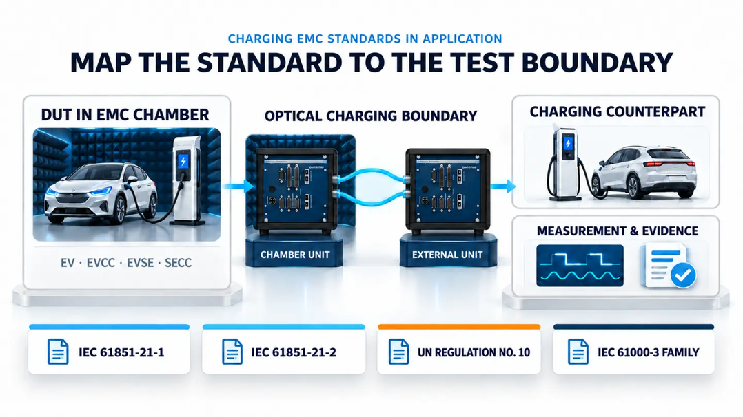
Vehicle and onboard charger
Keep the EVSE-side counterpart and charging communication available while the complete vehicle or vehicle-side electronic subassembly is tested.
Off-board charging equipment
Keep the EV-side counterpart outside while the charging station, SECC or off-board subsystem is operated in the required mode.
Vehicle approval context
Support the defined charging harness and active operating state. The exact regulatory series, annex and laboratory geometry remain part of the approval plan.
Harmonics and flicker
Maintain communication while dedicated grid and measurement equipment evaluates AC mains behaviour. EMC Link does not create the power-quality result.
Four practical topologies
Use the same optical product boundary with real or simulated partners.
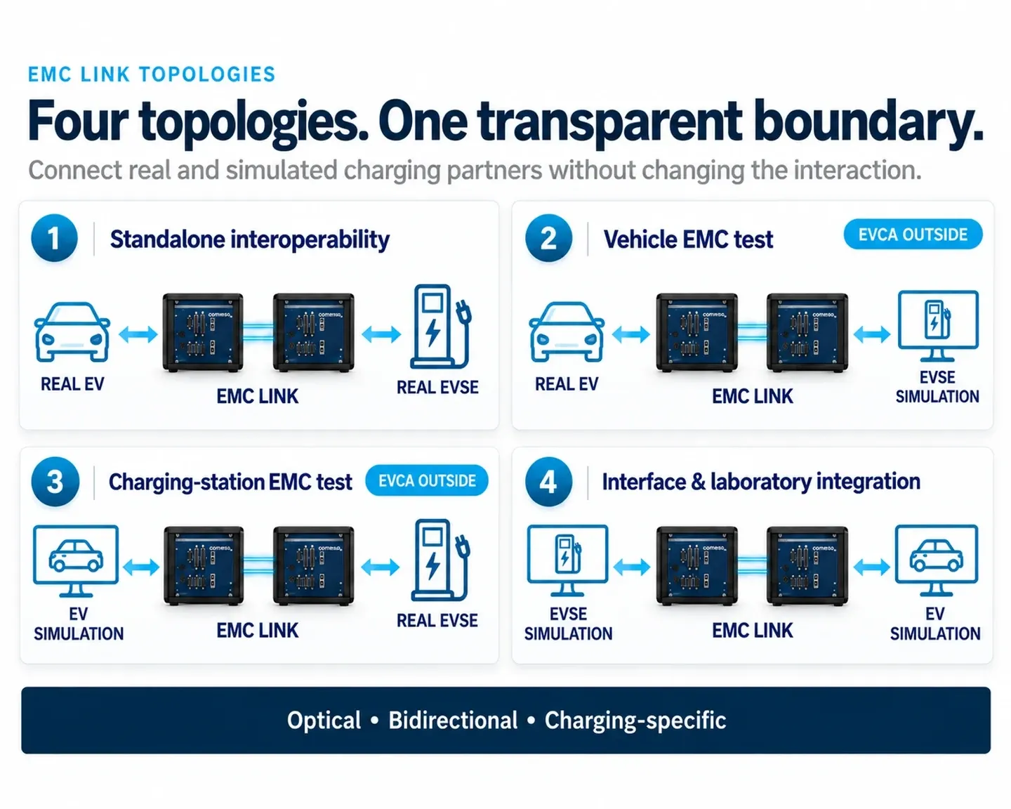
Real EV and real EVSE
Standalone operation keeps both real implementations active.
Real EV with EVSE simulation
Vehicle-side chamber test with a controlled charging-station counterpart outside.
Real EVSE with EV simulation
Charging-station-side chamber test with a controlled vehicle counterpart outside.
Interface validation
Simulation-to-simulation and component-level setups for a defined boundary.
Transparent signal transport
Carry the charging-specific context through optical media.
The applicable path depends on the selected charging technology and released module configuration.
PLC communication
High-level powerline communication for applicable charging technologies.
Low-level charging signals
Control Pilot (CP)/Proximity Pilot (PP), CS1/CS2, CC1/CC2, CE/ID and temperature according to configuration.
Auxiliary handling
Relay contact for digital control of the opposite-side 12 V auxiliary environment where configured.
Ethernet and CAN
Supporting data paths for the selected test architecture.
Preserve the signal paths the charging interaction actually needs
- High-level communication
PLC charging communication through the optical path
- Low-level charging signals
CP / PP · CS1 / CS2 · CC1 / CC2 · CE / ID · temperature
- Auxiliary control
Charging-specific AUX handling through digital relay control
- Vehicle and test interfaces
CAN and Ethernet for the configured laboratory setup
- Test intelligence outside
EVCA and comframe logging, analysis, simulation and evidence
Standalone or integrated
Use EMC Link alone or connect the complete EVCA evidence workflow.
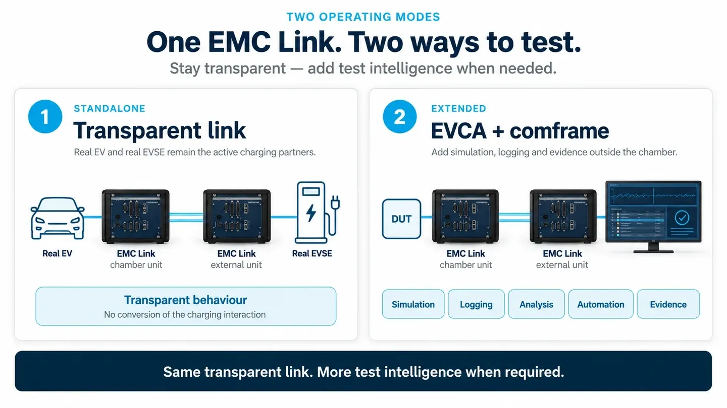
Real EV and real EVSE remain the partners.
Use the optical link to preserve the supported charging paths across the chamber boundary without adding a simulation system.
EVCA provides the real or simulated counterpart.
Add comframe logging, analysis, debugging and simulation control outside the chamber according to the selected EVCA configuration.
Technology-specific modules
Move between supported charging families without rebuilding the chamber concept.
The current public brochure identifies the following technology paths. The quotation defines the actual modules, connectors and software compatibility.
One chamber workflow across multiple charging technologies
- AC
Control Pilot and charging-state behaviour
Software-controlled selection reduces chamber interruptions and hardware changes.
- CCS / NACS
CP plus PLC communication for supported configurations
Software-controlled selection reduces chamber interruptions and hardware changes.
- CHAdeMO
Charging-specific signals and CAN communication
Software-controlled selection reduces chamber interruptions and hardware changes.
- GB/T DC
CC1 / CC2, CAN and configured interface signals
Software-controlled selection reduces chamber interruptions and hardware changes.
MCS remains a separate configuration path
Its communication, signals, cooling and high-power architecture require dedicated product definition.
Control pilot and proximity paths
Combo 1 and Combo 2 with PLC
Configured charging paths and PLC
Technology-specific low-level and CAN paths
China-specific signal and CAN environment
Separate product and configuration path
Configuration inputs
Specify the chamber boundary before selecting modules.
- 1
DUT, standard and condition
Vehicle, OBC, inlet, controller, EVSE or module, plus IEC 61851-21-1, IEC 61851-21-2, UN R10 or the applicable laboratory procedure.
- 2
Charging counterpart
Real EV, real EVSE, EV simulation or EVSE simulation.
- 3
Technology and signal depth
Connector family, PLC (power line communication), low-level signals, CAN, Ethernet, temperature and auxiliary requirements.
- 4
Chamber integration
Fibre routing, feedthroughs, filtered 12 V supply, artificial network or AAN, harness geometry, external power and safety.
- 5
Evidence and software
Standalone operation or EVCA/comframe logging, analysis, control and reporting.
Configure the optical link around the actual chamber test
- DUT in the chamber
Vehicle, inlet, controller or charging station
- Counterpart outside
Real EV / EVSE or EVCA simulation
- Charging technology
AC, CCS / NACS, CHAdeMO, GB/T DC or separate MCS path
- Transparent signals
PLC, low-level charging signals, CAN, Ethernet and AUX
- Environment
EMC or climate chamber, supply filtering and fibre routing
- Evidence
Standalone path or EVCA + comframe logging, analysis and reports
Defined EMC Link configuration + compatible EVCA path + approved chamber setup
Product boundary and technical scope
Keep transport, test intelligence and charging power as separate responsibilities.
On smaller screens, scroll the table horizontally to see every column.
| Layer | EMC Link role | Provided elsewhere | Configuration rule |
|---|---|---|---|
| Charging communication | Transparent transfer of released PLC and supporting paths | Decoding, analysis, manipulation and simulation by EVCA/comframe | Protocol and software release must match the selected modules |
| Low-level signals | Technology-specific transport of configured signal paths | Test logic, stimulus and verdicts by the connected system | CP/PP, CS1/CS2, CC1/CC2, CE/ID and temperature are technology-dependent |
| Chamber connection | Chamber-side unit, external unit and two optical fibres | Feedthroughs and facility integration by the laboratory | Routing and filtered 12 V supply must be defined before installation |
| Charging power | No power conversion or high-power transfer | Sources, loads, cables, cooling, interlocks and safety systems | Power architecture remains a separate approved workstream |
| Evidence | Preserves the communication path | Logging, correlation, automation and reports by EVCA/comframe | Required channels and output must be specified with the application |
| Standard and verdict | Keeps the defined charging interaction available during the test | RF generation, receivers, artificial networks, grid and power-quality instruments, laboratory assessment and approval | Exact document, edition, series, DUT mode, limits and verdict method remain external to EMC Link |
Maintain a transparent charging-specific optical path.
- Connect chamber-side and external interface units
- Support standalone and integrated topologies
- Keep complex test equipment outside
- Reduce interruptions and test restarts caused by the communication boundary
Replace the charging simulator, analyser or power system.
- It does not transfer charging power
- It does not independently decode or analyse protocols
- It does not independently manipulate or simulate charging behaviour
- It does not imply every technology is present in one fixed base configuration
EMC Link documents and related applications
Move from hardware selection to the complete EMC test method.
DUT boundary, EV and EVSE directions, chamber workflow and evidence methodology.
PlatformCharging counterpart, measurement, simulation and system integration.
SoftwareLogging, synchronised analysis, automation and reporting outside the chamber.
BrochurePublished architecture, technologies, signal scope and setup notes.
IEC 61851-21-1, IEC 61851-21-2, UN R10, harmonics, flicker and exact edition context.
Frequently asked questions
EMC Link product FAQ
What is EMC Link?
EMC Link is a charging-specific optical interface that transports selected communication and signal paths between a chamber-side unit and an external unit so a real or simulated charging partner can remain outside the interference zone.
Can EMC Link work without an EVCA test system?
Yes. In standalone mode, a real EV and real EVSE can remain the active partners. In integrated mode, EVCA and comframe add simulation, logging, analysis and control.
Which paths can be transported?
The public brochure identifies PLC, technology-specific low-level signals, temperature and auxiliary handling, Ethernet and CAN. The actual set depends on the selected technology and released configuration.
How many optical fibre cables are used?
The published chamber setup uses two optical fibre cables to connect into and out of the chamber.
How is the chamber-side unit powered?
The public brochure describes a filtered 12 V DC supply inside the chamber. The exact facility connection and filtering remain part of the approved laboratory integration.
Which charging technologies are covered?
The public brochure lists AC, DC CCS Combo 1 and Combo 2, NACS, CHAdeMO and GB/T DC. MCS is available separately.
Product configuration
Define the required configuration for the real test boundary.
Share the DUT, interfaces, ranges, software and evidence required from this product.