
Standards & Knowledge / Resources and tools
Battery Cell Simulation in Detail
Test the BMS with a virtual battery you can control.
A battery management system acts on cell voltage, current, temperature, timing and communication. Virtual battery cells make those inputs, boundaries and faults safe, repeatable and automatable, from a single monitoring IC to a complete high-voltage BMS HiL.

Start with the decision chain
The BMS sees the Battery as a System, not a Single Value
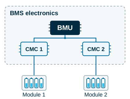
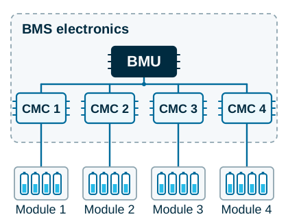
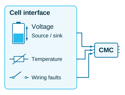
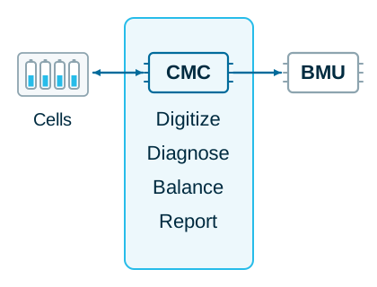
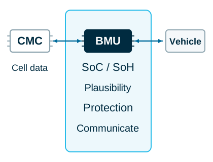
A modern battery pack consists of cells, modules and multiple layers of monitoring and control. Cell Management Controllers (CMCs), also referred to as Cell Supervising Circuits (CSCs), monitor individual cell voltages and temperatures. A central Battery Management Unit (BMU), as part of the overall Battery Management System (BMS), combines these measurements with pack current, isolation status, contactor states and communication data to assess the battery’s operating condition, ensure safe operation and determine its allowable operating limits.
Test the complete chain. Control the physical inputs, observe the distributed measurements and verify the resulting BMS decision.
1. CMC + Cell Module

2. BMU + 2 CMCs + 2 Cell Modules
3. BMS with multiple CMCs
Cell and Sensor Level
CMC / Cell Monitoring Level
BMU / System Level
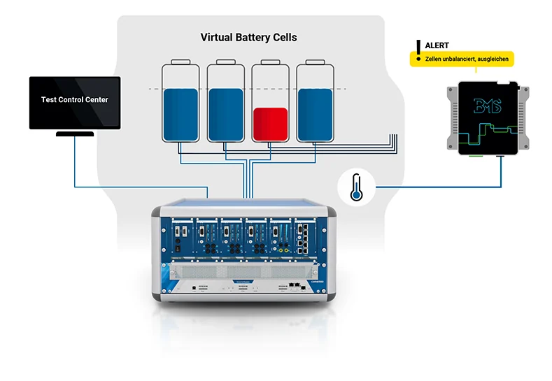
Virtual battery cells
Replace chemical uncertainty with controlled electrical behaviour.
Real cells are essential for battery characterization. They are a poor source for many BMS boundary and fault tests because their state, ageing and temperature drift. Hazardous conditions are difficult to reproduce, and automation is constrained. A virtual cell establishes a deterministic interface to the BMS.
Passive and active balancing
The test system must reproduce the current path, not only the voltage setpoint.
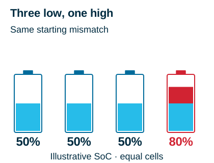
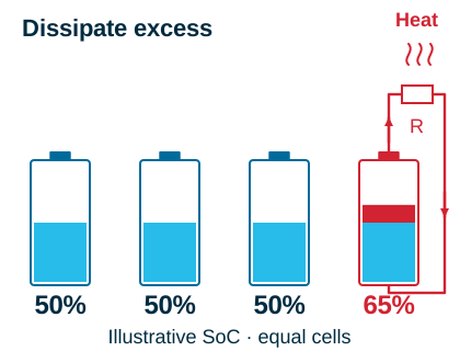
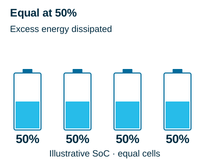
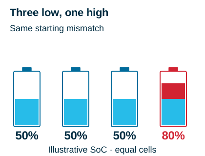
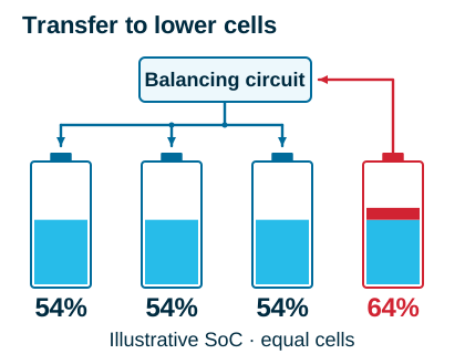
Cell variation causes different charge levels within one series stack. The BMS uses balancing to bring those states closer together. A valid test challenges thresholds, current direction, amplitude, timing, completion criteria and the effect on neighbouring channels.
Passive Cell Balancing
1. Initial state
2. Balancing process
3. Balanced state
Active Cell Balancing
1. Initial state
2. Balancing process
3. Balanced state
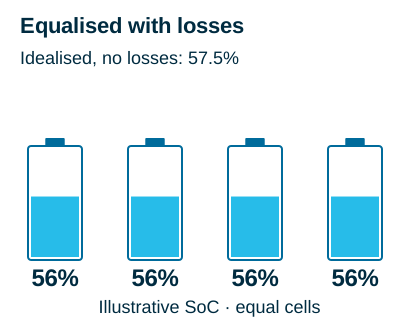
Schematic examples with equal-capacity cells; the illustrated SoC levels are not measured product performance. In a BMS test, correlate cell settings, balancing current and diagnostic response over time.
Integrated fault simulation
Introduce the failure at the same electrical boundary the BMS monitors.
Fault insertion is strongest when it is close to the individual cell channel. This preserves the configured voltage path and makes the fault attributable to one defined input instead of an improvised external wiring change.
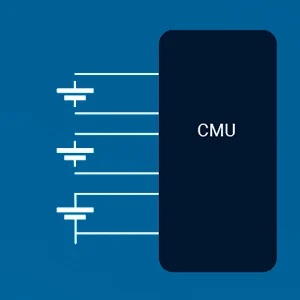
Open circuit
Represent a broken sense lead, connector problem or material fatigue and verify detection, timing, latching and recovery.
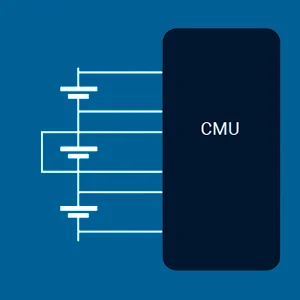
Short circuit
Represent a faulty cell path or electronic defect while maintaining a controlled and repeatable laboratory condition.
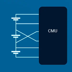
Polarity reversal
Challenge cabling, assembly and plausibility diagnostics with a defined reversal at the selected channel.
Sensor and leakage faults
Combine temperature-sensor opens or shorts with quiescent and leakage-current observation where the selected configuration supports it.
Development bench
Move from manual fault hunting to approved test states.
Compact and rack-based systems can bring cell simulation, fault insertion and control interfaces into the same test architecture. The exact faults, current paths and isolation concept remain configuration specific.
Review the current BCS platform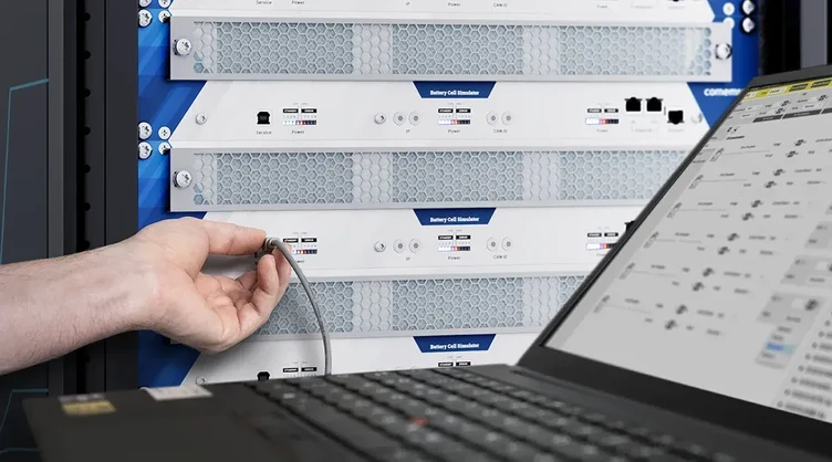
Precision and traceability
A battery model is only as credible as the electrical output that implements it.
Many cell chemistries have a comparatively flat voltage curve across part of the usable SoC range. In that region, a small voltage error can create a much larger uncertainty in the estimated state. Precision must therefore hold while the channel sources or sinks balancing current, across the configured stack and over the intended test duration.
Current product context. The public BMS Tester page describes scalable systems from 12 to 300 cells, 0.1 to 8 V per cell and system voltages up to 1,500 V. Current ranges and accuracy depend on the selected BCS variant. The released quotation and technical specification remain decisive.

Current measurement
Balancing is a time-domain event.
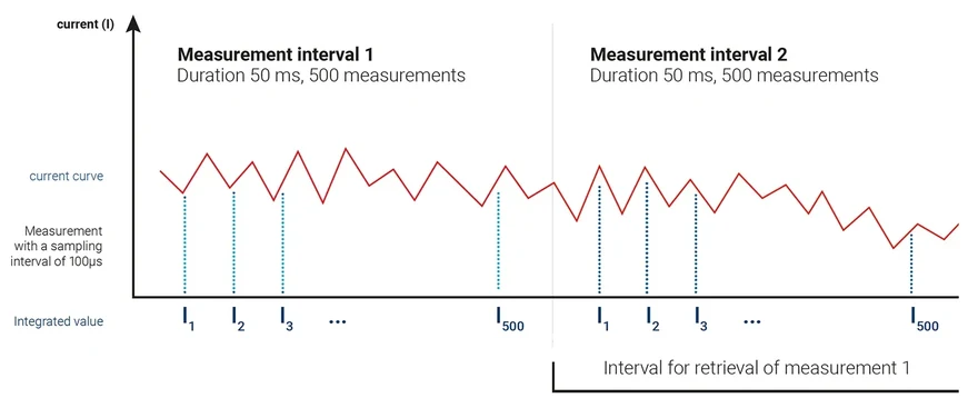
Quiescent current can expose unwanted consumption while the BMS should be inactive. Leakage current can reveal defective outputs or incorrect software control. During balancing, current integration can show how much charge moved over a defined interval.
-
1
Set the cell state
Define the voltage, temperature and operating mode before the balancing command.
-
2
Capture the current
Measure direction and magnitude with the range and resolution required by the DUT (device under test).
-
3
Integrate over time
Optional coulomb measurement converts repeated samples into transferred charge.
-
4
Verify the decision
Compare the BMS command, actual path, thresholds and final diagnostic state.
Thermal input and environment
Temperature is a control input, a plausibility signal and a safety boundary.
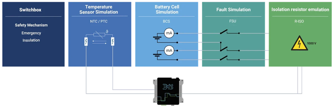
The BMS uses cell and pack temperatures to limit charge and discharge, coordinate cooling and recognize unsafe states. Isolated NTC and PTC emulation replaces the physical sensor with a programmable resistance path and enables sensor faults that would be difficult to reproduce safely with a real pack.
Temperature profiles
Move individual channels or groups through defined temperatures and gradients while observing limits and derating.
Open and short
Verify sensor diagnostics, substitute values, timing, latching and recovery after a defined electrical fault.
Climate and EOL
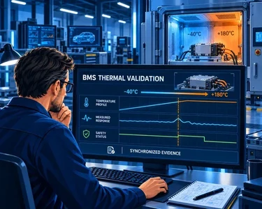
Combine signal simulation with climate chambers and, where required, multiplexing for repeated tests across DUTs and temperatures.

Automation and battery models
Static values prove thresholds. Closed-loop models prove behaviour.
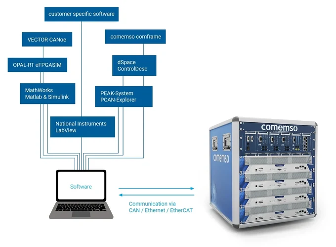
A BMS test strategy normally uses both. Deterministic static sequences expose accuracy, boundaries and fault reactions. Dynamic battery models change cell values with SoC, SoH, current, temperature and BMS actions so algorithms can be evaluated in a closed loop.
Configure
Set cell count, limits, initial states, sensors, faults and DUT identification.
Connect
Use the released CAN, Ethernet or EtherCAT interface and the required real-time environment.
Execute
Run static sequences, parameter sweeps, dynamic models and fault campaigns.
Preserve
Retain model, configuration, measurements, events and result with one test identity.
Design the BMS test bench
Specify the electrical boundary before selecting the rack.
A modular BMS HiL (hardware-in-the-loop) can start with a compact channel set and expand to a complete high-voltage stack. A correct architecture is defined by the DUT and the validation decision, not by one generic product list.
DUT scope
Monitoring IC, AFE (analogue measurement front end), CMC, central BMS, complete pack controller or integrated vehicle function.
Cell architecture
Channel count, voltage window, stack voltage, isolation concept and connector topology.
Balancing depth
Passive or active behaviour, source and sink current, low-current measurement and optional coulomb integration.
Sensors and faults
NTC or PTC channels, pack current, isolation, open wire, short circuit, polarity and project-specific I/O.
Dynamics and automation
Static sequences, closed-loop models, cycle time, CAN, Ethernet, EtherCAT, MATLAB/Simulink and reporting.
Lifecycle
Development, validation, endurance, climate, production, EOL (end-of-line), maintenance, calibration and future expansion.
From electrical channel to safe DUT access
Fault injection remains controlled only when the physical access path is controlled too.
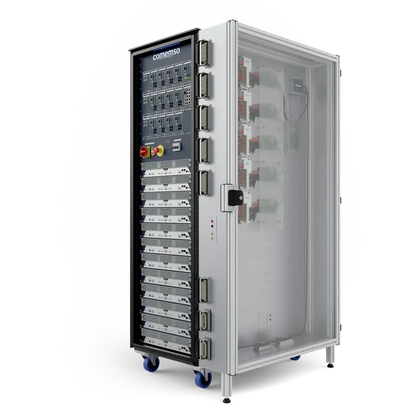
In a rack-based BMS HiL, the BMS and CMUs can be mounted on a threaded grid plate inside an interlocked side enclosure. Opening its door—or an integrated DUT drawer—interrupts the system enable chain, shuts down the complete setup and switches the BCS outputs to a de-energised state.
The safety chain in one view
- DUT mounted on a threaded grid plate
- Access door coupled to the BMS HiL interlock
- Door opening triggers system shutdown
- BCS outputs become de-energised
- Same principle available for integrated DUT drawers
Engineering boundary: The finished protection concept is defined by the delivered system, DUT, interfaces and project risk assessment.
Beyond the isolated BMS
Connect battery decisions to the application that depends on them.
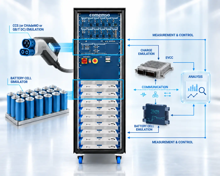
In an electric vehicle, the BMS exchanges limits and state information with the vehicle controller, OBC (onboard charger) and EVCC (vehicle-side charging communication controller). An integrated test bench can combine virtual battery behaviour with EV charging simulation to verify how a cell-level condition propagates into charging communication and vehicle-level action.
BMS Testing
Build the validation strategy from monitoring IC to complete battery application.
Integrated HiLEVCC + BMS
Verify the handoff between battery limits, OBC control and charging communication.
ProductBattery Cell Simulator
Review the current modular BCS platform and released configuration envelope.
EVCA
Add EV or EVSE (electric vehicle supply equipment, or charging station) communication simulation and synchronised charging evidence.
Source and product status
Use the guide for the method. Use the current release for the specification.
Based on comemso’s technical article on virtual battery cells. Check the current BCS specification, quotation and released documentation for product limits, options and interfaces.
Battery Cell Simulation in Detail
Official article covering monitoring, balancing, virtual cells, faults, precision, thermal signals and automation.
comemso BMS Tester
Current public BCS system range, interfaces and configurable functions.
LifecycleBCS SmartCal
Automated adjustment and calibration route for applicable Battery Cell Simulator systems.
DocumentBCS brochure
Current 2026 product overview. The quotation and released specification remain decisive for the selected system.
FAQ
Battery cell simulation, precisely bounded.
What is a virtual battery cell?
It is an electrically controlled channel that reproduces the voltage and relevant source or sink behaviour presented to one BMS cell input. Depending on the configured system, it can be combined with current measurement, temperature-sensor emulation and cell-level fault insertion.
Why not use real battery cells for every BMS test?
Real cells are required for electrochemical characterization, but many BMS boundary and fault scenarios are hazardous, slow, state dependent or difficult to reproduce. Virtual cells make those electrical inputs deterministic and automatable.
Can the same system test passive and active balancing?
Yes, when the selected BCS variant provides the required sink and source current ranges. Passive balancing primarily requires controlled current sinking. Active balancing can require both source and sink behaviour. The delivered current range is configuration specific.
Which cell faults can be simulated?
Published configurations can include open circuits, short circuits and polarity reversal. Sensor faults, isolation functions and additional I/O depend on the selected hardware and project scope.
Why is cell-voltage precision so important?
The voltage-to-SoC relationship can be comparatively flat across part of the usable range. A small voltage error can therefore obscure the BMS threshold or estimation behaviour being evaluated. Accuracy also has to remain valid under balancing current and across the complete configured stack.
What is coulomb measurement used for?
It integrates measured current over time so balancing charge transfer can be evaluated as a quantity, not only as an instantaneous current value. Availability, timing and range depend on the selected BCS option.
BMS-controller test planning
Replace real cells with a safe, controllable test boundary.
Specify the BMS, emulated cell and sensor channels, controlled faults and required evidence.