

Applications / Megawatt Charging System testing
Megawatt Charging System Testing for EV and EVSE
Megawatt Charging System (MCS) testing brings together high current, cooling and communication. Test the truck or charging station under defined conditions before relying on the complete real-world charging pair.
The operational reason for MCS
For long-haul transport, charging must fit the operating window.
Depot charging remains important. Long-haul operation adds another constraint: the required energy must be transferred inside a scheduled stop instead of extending vehicle downtime. That makes charging speed an operational requirement rather than a convenience feature.
Illustrative energy comparison. At 1 MW, 45 minutes corresponds to approximately 750 kWh before charging-curve and system losses are considered. Transferring the same theoretical energy through a 230 V, 13 A single-phase household outlet would take roughly ten days. The comparison explains scale. It is not a vehicle charging-time specification.

MCS is more than a thicker charging cable
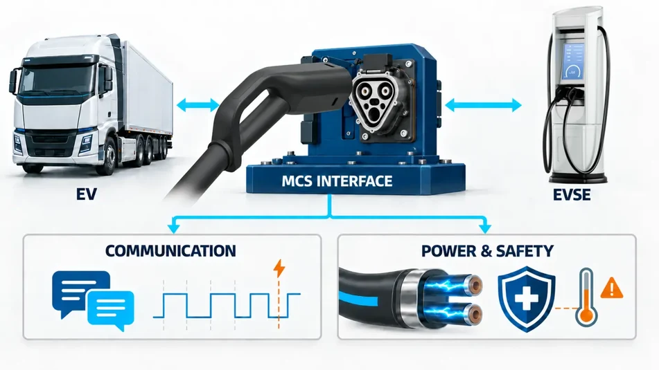
Power, communication, cybersecurity, safety and cooling must describe the same state.
The difficult part is not only transferring more current. The MCS coupler, physical link, high-level communication, certificates, low-level states, locking, temperature measurement, cooling and high-voltage path must transition in the right sequence and react coherently to every limit and fault.
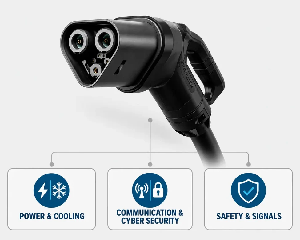
Power
Voltage, current, pre-charge, ramps, requested limits, contactors, reduction and safe shutdown.
Communication
10BASE-T1S, ISO 15118-20 message sequences, timing and controller state transitions.
Cybersecurity
TLS, certificates, keys and secure session behaviour within the released implementation.
Safety and signals
Charge Enable, Insertion Detection, locking, auxiliary supply, isolation and controlled recovery.
Cooling
Connector and inlet temperature, coolant behaviour, derating and long-duration operation.
Controlled reality for a system still being industrialised
Real vehicles and chargers are essential. They are poor tools for creating every development condition.
A prototype truck is expensive and not always available. A prototype charging station is changing at the same time. A real failure is difficult to schedule, unsafe to provoke and rarely repeatable under identical conditions.
Cannot be the deterministic source of every boundary and fault.
Its own changes make root-cause comparison difficult.
Needs a controlled laboratory representation before release.
Development needs reproducible reality. Control the missing partner, repeat the same condition and preserve the evidence.
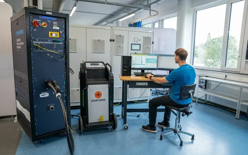
Six coordinated MCS test domains
Separate the layers for diagnosis. Recombine them for the charging decision.
Each domain has its own requirements and failure modes. A complete test proves that the full interface reaches the intended state at the intended time.
Power transfer
Pre-charge, voltage and current ramps, contactors, isolation, reduction, stop and recovery.
High-level communication
ISO 15118-20 services, messages, timing, certificates and EVCC (vehicle-side charging communication controller) or SECC (station-side charging communication controller) transitions.
10BASE-T1S
Link establishment, frame transport, disturbances and recovery below the application protocol.
CE and ID signals
Charge Enable and Insertion Detection states, timing, interruption and forbidden combinations.
Connector and thermal
Mating, locking, temperature sensing, cooling, derating and prevention of disconnection under load.
Safety and interoperability
Protective states, secure sessions, cross-vendor behaviour, fault reactions and safe recovery.
One interface. Different devices under test.
Vehicle, charging-station and component teams need different evidence from the same MCS architecture.
EVCC, inlet, battery and complete vehicle
Test MCS EVSE (electric vehicle supply equipment, or charging station) behaviour, CE and ID, high-voltage sequencing, requested limits, battery permission, thermal coordination and safe stop before relying on public charging trials.
SECC, dispenser, power cabinets and cooling
Represent heavy-duty vehicle and battery requests, challenge unusual states and evaluate output, protection, derating and recovery without depending on one truck.
EVCC, SECC and communication stack
Develop ISO 15118-20, certificates, 10BASE-T1S and state machines against deterministic partners before full hardware is available.
Coupler, inlet, cable and cooling
Relate insertion, locking, temperatures, coolant behaviour and electrical contact to the controller response.
Neutral, traceable test partners
Switch between EV, EVSE and real-pair roles while retaining synchronised evidence, configurations and reports.
Where large batteries meet costly downtime
Megawatt charging extends beyond the motorway.
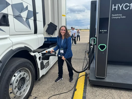
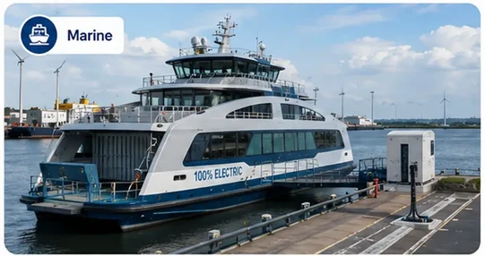
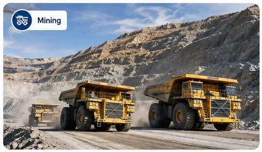
Long-haul trucks remain the primary reference case. Marine, mining, off-highway and other heavy-duty systems add different duty cycles, environments and acceptable failure responses.
Four test directions
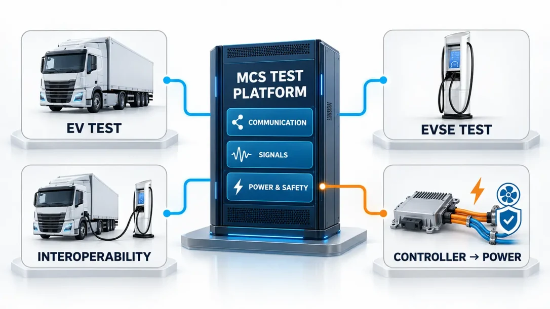
Choose the direction from the device under test.
The simulated partner creates repeatable normal, boundary and fault conditions. Real vehicle and charging-station pairings then prove interoperability.
EV testing with EVSE simulation
Control charging-station communication, CE and ID, timing, power conditions and failures while measuring the vehicle response.
EVSE testing with EV simulation
Control vehicle requests, battery limits and abnormal states while measuring output, safety and recovery.
Interoperability with real partners
Observe a real EV and EVSE together, align every available layer in time and preserve the case for root cause and regression.
Controller-to-full-power scaling
Begin with EVCC or SECC software, then add physical link, low-level signals, power, cooling, EMC and environmental hardware.
Build evidence from the lowest useful layer
Use the simplest method that can expose the current risk.
More realism is useful only when it changes the response being evaluated. Preserve the same requirements and scenarios as the test moves toward full-power operation.
Communication-only development
Develop EVCC and SECC software, certificates, services and state machines before full power is required.
Signal-state testing
Set CE and ID states and timing precisely, including interruption, forbidden zones and inconsistent combinations.
Automated protocol scenarios
Repeat normal, boundary and supported non-conform communication behaviour across releases.
Full-power and thermal validation
Add source or load hardware, high-voltage measurement, liquid cooling and long-duration duty profiles.
Fault and recovery testing
Challenge communication, signals, temperature, power and safety conditions one layer at a time.
Cross-vendor interoperability
Use real pairings to verify the complete interface and transfer difficult cases into repeatable engineering evidence.
Complex under the hood. Manageable in the workflow.
Keep certificates, states, signals, power and results connected.
MCS adds application communication, single-pair Ethernet, secure sessions, multiple certificates and keys, low-level states, temperature channels and high-power hardware. The engineer should not have to reconstruct the meaning of the test from unrelated tools after every run.
- 1
Configure the test
DUT, partner, standards edition, signal states, certificates, power and thermal conditions.
- 2
Execute the controlled condition
Run the same scenario under attributable hardware and software versions.
- 3
Correlate the layers
Relate communication, CE and ID, temperature, voltage, current and safety states.
- 4
Preserve the decision
Store the measurement, expected relationship, deviation and report for regression.
Development value. The objective is not more amperes in isolation. It is earlier fault discovery, repeatable testing and a safer path from controller development to field operation.
From development concept to practical testing
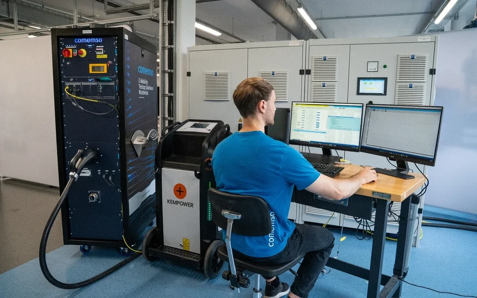
Not a future study. Already used in real projects and cross-vendor environments.
Explore MCS customer projects, European charging-station tests and comemso participation in CharIN Testival Europe 2026 in Arnhem.


Standards overview
Specify the exact edition at every interface layer.
MCS standards and implementations continue to evolve. Check the applicable editions, profiles, released functions and implementation limits for your selected EVCA MCS configuration.
IEC TS 63379
Connection system, vehicle inlet, plug, cable and associated mechanical interface.
IEC 61851-23-3
MCS-specific low-level interface, including Charge Enable and Insertion Detection.
ISO 15118-10
Two-wire single-pair Ethernet physical and data-link layer based on 10BASE-T1S.
ISO 15118-20
Charging and protocol-level BPT services stay within the released communication scope. Physical reverse energy flow requires separately configured external source/load equipment.
ISO 5474-3
Vehicle-side requirements relevant to the high-voltage charging interface and safety concept.
Scope rule. A reference to a standard does not mean that every optional service, certificate workflow or future Test Library is released in every system configuration.
Application first. System second.
Translate the MCS risk into a test-system specification.
Define the DUT, simulated role, standards edition, coupler or inlet, signal access, power profile, cooling, safety, evidence and lifecycle. Only then select the physical EVCA MCS configuration.
DUT and direction
EV, EVSE, EVCC, SECC, connector system or subsystem.
Communication test scope
10BASE-T1S, ISO 15118-20 services, TLS and certificate scope.
Interface
Coupler, inlet, CE, ID, auxiliary voltage and temperature access.
Power and duty
Voltage, current, maximum power, duration and repetition.
Cooling and safety
Cable, connector, flow, temperatures, interlocks and safe states.
Evidence and lifecycle
Controller bench, full-power validation, interoperability, production and field.
Frequently asked questions
MCS testing FAQ
What is Megawatt Charging System testing?
It is the coordinated validation of the MCS vehicle, charging-station and shared interface across high-level communication, 10BASE-T1S, CE and ID signals, connector and inlet states, temperature, cooling, power transfer, safety and interoperability.
Why is MCS testing different from CCS testing?
MCS introduces a dedicated connection system, single-pair Ethernet communication, MCS-specific low-level states, high-current thermal management and different power and safety requirements. The test architecture must coordinate these layers instead of scaling one CCS current value.
Can MCS vehicles be tested before a public MCS charger is available?
Yes. A controlled MCS EVSE simulation can provide the communication, CE and ID environment and can coordinate the required external source and cooled interface for the selected vehicle test depth.
Can an MCS charging station be tested without a real truck?
Yes. A controlled MCS EV simulation can represent vehicle communication, battery requests, low-level states and supported fault conditions while separately configured external DC source/load equipment represents the battery-side energy path.
When is communication-only testing useful?
It is useful for EVCC and SECC software, certificates, 10BASE-T1S, ISO 15118-20 and low-level state development before voltage, current and full thermal hardware are required.
How should interoperability be added?
First establish deterministic EV and EVSE tests. Then use real cross-vendor pairings with synchronised evidence to identify implementation differences and convert difficult cases into repeatable reusable test records.
MCS test planning
Define communication, interface and power scope separately.
Specify the DUT role, MCS interface, thermal context and separately configured source/load equipment.