
Products / EVCA / EVCA Flex
EVCA Flex: High-Power EV and EVSE Test System
Test a vehicle against a simulated charging station, or test a station against a simulated vehicle. EVCA Flex coordinates charging communication and signals with the external power equipment and measurement or fault modules selected for your laboratory test.
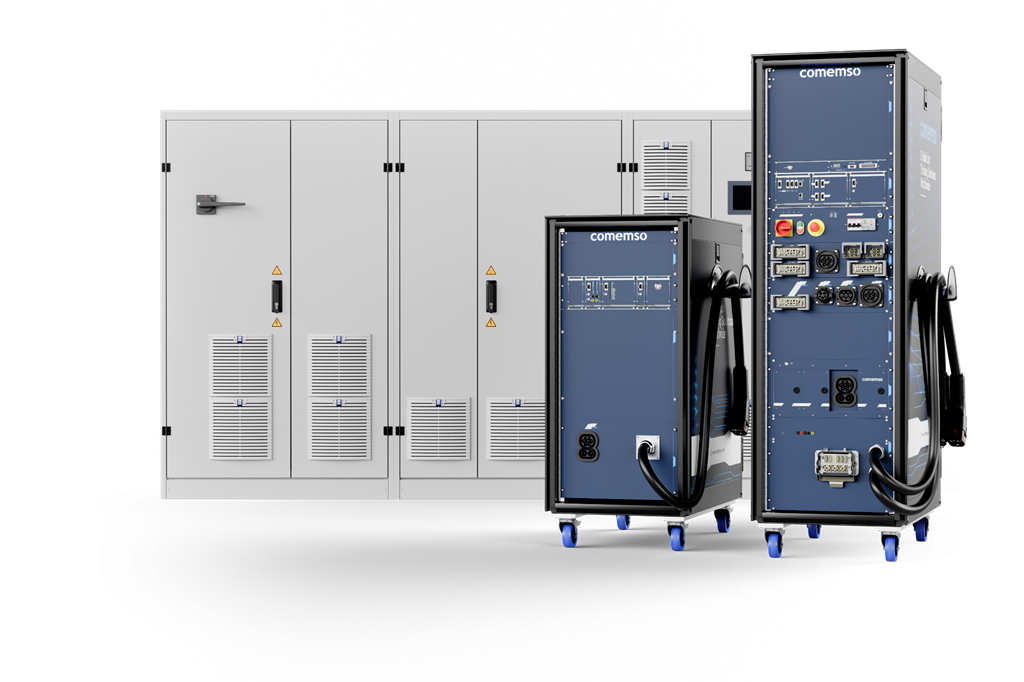
Which Flex test setup fits your task?
Basis and scope
The standard describes requirements; the agreed hardware, software and test cases define the delivered system.
Text updated:
Modular high-power laboratory platform
Build the test system around the charging risk, not around one fixed power cabinet.
A high-power charging test is useful only when communication, low-level states, contactors, source or load behaviour, measurement, safety supervision and evidence respond as one system. EVCA Flex keeps the charging-specific hardware and software workflow stable while the project-specific power path can change.
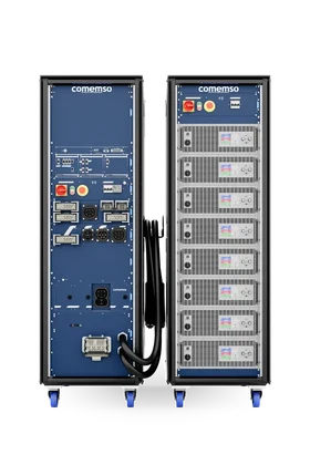
The modular rack and cassette architecture supports hardware replacement and expansion without returning or replacing the complete test environment. This reduces downtime when connectors, standards, voltage classes or test objectives evolve.
One platform. Both sides of the charging interface.
Keep one analysis workflow while the simulated charging partner changes.
EVCA Flex is configured around the device under test. The power equipment, connector, low-level interface and simulation role follow that decision.

EVCA Flex represents the charging station.
Coordinate EVSE (electric vehicle supply equipment, or charging station) communication, low-level states and the selected source so the EVCC (vehicle-side charging communication controller), charging inlet, onboard systems and complete vehicle can be challenged under controlled conditions.
- AC and DC EVSE simulation
- Source and grid-emulator integration
- EVCC, BMS, OBC and vehicle-state correlation
- Conformance, robustness and regression campaigns

EVCA Flex represents the vehicle and battery side.
Coordinate EV communication, battery requests, the selected load or bidirectional supply and the released fault modules required for charger development and verification.
- Configurable EV and battery behaviour
- Load or battery-emulator integration
- Output control, protection and shutdown reaction
- IEC 61851-23 and project-specific electrical testing
Modular system architecture
Separate reusable charging intelligence from project-specific power and fault hardware.
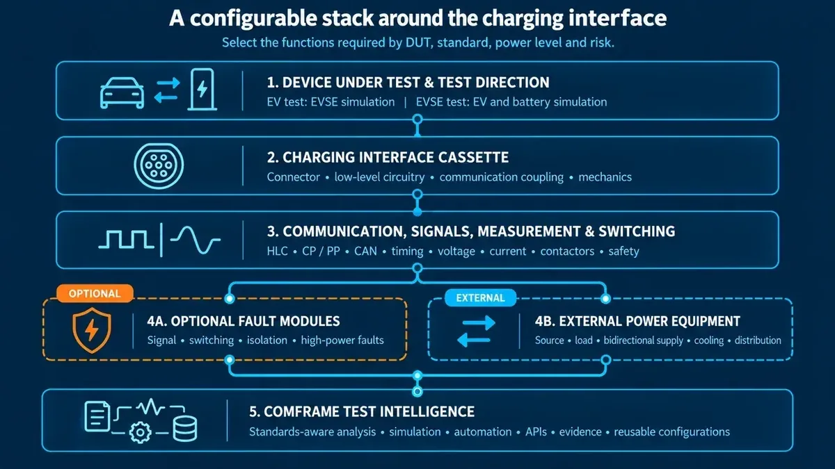
The physical charging interface, communication, low-level signals, measurement, switching, external power and software remain coordinated, but they do not have to be locked into one monolithic cabinet.
EV or EVSE simulation
Protocol, low-level states, connector context and operating behaviour are selected around the DUT.
Charging connectors and measurement
Use the released connector, voltage class, current path and measurement channels required by the project.
External source, load and optional switching
Integrate power equipment and fault hardware without changing the charging-specific software workflow.
comframe, Test Libraries and automation
Configure, analyse, automate and preserve evidence from the complete charging event.
EVCA Flex with the IEC 61851-23 rack
Provoke the electrical fault. Measure how the EVSE responds.
EVCA Flex with dedicated IEC 61851-23 switching and fault hardware addresses the full Annex CC.7.5 test scope in the matching system configuration. comemso demonstrated these test cases on a customer’s charging station in its own laboratory. Define the standard edition, fault cases and operating points for your project.

Charging simulation, interfaces, synchronised measurement, power coordination and comframe.

Dedicated switching and fault paths for the selected released test scope.
Responsibility matrix
Make every element of the IEC 61851-23 test path explicit.
On smaller screens, scroll the table horizontally to see every column.
| Test function | Primary system element | Project definition |
|---|---|---|
| EV simulation and charging communication | EVCA Flex and comframe | Charging family, protocol edition, certificates, messages and low-level behaviour |
| Voltage, current and power coordination | EVCA Flex with external source, load or bidirectional system | Operating quadrant, dynamics, maximum and continuous envelope, cooling and facility limits |
| Selected IEC 61851-23 electrical paths | IEC 61851-23 rack where required | Released switching and fault modules mapped to the applicable test cases |
| Waveform acquisition | External oscilloscope and measurement equipment | Channels, probes, bandwidth, trigger conditions, isolation and data handover |
| Test sequence and verdict | Conformance Test Library and comframe | Standard edition, annex, Test Library release, project parameters and report requirements |
| Power absorption | External load or bidirectional power system | The load must cover the charger power required by the planned test condition |
Plan a demonstration with your charging station
Bring your EVSE test task to our laboratory. We define the required fault cases, voltage, current and power range, switching and protection hardware, source or load, and measurement channels. Agree the TestLib version and software workflow, then assess the DUT response in the demonstrated setup.
Discuss the test scope and demonstrationIEC 61851-23:2023 test structure
Select the applicable system and annex before selecting the hardware.
IEC 61851-23:2023 distinguishes DC charging systems A, B and C in Annexes AA, BB and CC and includes additional general test topics. A product claim must identify the applicable system, standard edition, Test Library and released hardware scope. The existence of an annex is not a blanket claim that every delivered configuration covers every case.
System A. CHAdeMO
Test cases for the CHAdeMO charging-system path. Confirm the supported CHAdeMO release and hardware configuration.
System B. GB/T DC
Test cases for the DC GB/T charging-system path. Confirm the released protocol, connector, low-level and electrical scope separately.
System C. DC CCS
The combined Flex, Test Library and IEC-rack path is configured for DC CCS verification according to the released project scope.
General topics and test conditions
Include the applicable general requirements, measurement methods and setup conditions in the complete project definition.
- 1
Select the standard scope
Define edition, system, annex and device-under-test role.
- 2
Map the test cases
Separate software-controlled sequences from cases that require dedicated electrical hardware.
- 3
Configure the physical path
Specify Flex rack, IEC rack, external load, oscilloscope, protection and facility interfaces.
- 4
Execute one synchronised test
Run communication, signals, electrical conditions and measurement under coordinated control.
- 5
Preserve measurements linked to their test conditions
Store verdicts, traces, waveforms, limits, configuration and report context together.
Power and controlled electrical faults
Qualify voltage, current, power, duty and fault energy as separate dimensions.
A mathematically possible voltage-current product is not automatically a continuous operating point. The complete configuration must account for source or load capability, cable and connector limits, cooling, switching energy, facility infrastructure and protection.
Published CCS and NACS high-voltage range
Final voltage range depends on the selected charging interface and complete system configuration.
Published high-current range
Higher current ratings remain project-specific and must be confirmed in the released quotation.
Published short-circuit configuration
Controlled short-circuit testing during charging requires the approved topology, hardware, limits and operating procedure.
Source, load or bidirectional system
Select the dynamics, operating quadrant and power envelope that match the device under test.

Message content and timing
Challenge supported protocol variables, delays, missing messages and deliberately nonconforming behaviour.
Charging signals and states
Apply released Control Pilot (CP), Proximity Pilot (PP) and technology-specific state scenarios at the interface where the DUT must react.
Contactors and isolation-related conditions
Coordinate the released switching paths, measurements and safe shutdown sequence.
Controlled high-power fault path
Use only the approved hardware, energy limits, protection concept and documented operating procedure.
One synchronised evidence base
Find the first meaningful deviation, not only the final shutdown.
Separate instruments produce separate clocks and separate traces. EVCA Flex and comframe preserve cause and effect across communication, low-level states, voltage, current, fault command, switching and DUT reaction.
- High-level communicationMessages, sequence, timing, TLS and certificate context according to the configured scope.
- Low-level interfaceCharging states, connection conditions and released signal measurements.
- Power behaviourRequested and measured voltage, current, source or load response and shutdown.
- Test actionFault trigger, switching command, test step, expected condition and actual reaction.
From test objective to released laboratory configuration
DUT direction
EV, EVSE, controller or subsystem
Charging interfaces
AC, CCS, NACS, CHAdeMO or GB/T
Power envelope
Voltage, current, direction, dynamics and cooling
Fault depth
Protocol, signals, switching and high-power faults
Automation
Libraries, cycles, APIs, evidence and reports
Environment
HiL (hardware-in-the-loop), EMC, climate, safety and upgrade path
Selected EVCA Flex hardware + external power + comframe capabilities + approved safety concept
Relate measurements and protocol events to expected limits and highlight deviations automatically.
Configure supported message content, timing and deliberately nonconforming partner behaviour.
Execute versioned procedures with automated steps, verdicts and reports according to the released scope.
Run saved charging cycles, variants, endurance sequences and unattended campaigns.
Field to labReproduce supported field behaviour actively at the physical charging interface.
Coordinate supported source, load, HiL and automation systems without rebuilding the charging domain.
Charging standards and system boundaries
Use EVCA Flex for the configured AC and DC charging families. Use EVCA MCS for the dedicated MCS architecture.
Connector hardware, protocol releases, TLS and certificate functions, power class, fault modules and Test Libraries are independent configuration decisions. The exact released scope belongs in the quotation and system specification.
AC and DC charging
IEC 61851-1, IEC 61851-23, DIN 70121, ISO 15118 including applicable ISO 15118-20 scope, SAE J1772 and selected NACS interfaces.
CAN-based DC charging
EV and EVSE simulation, communication analysis, measurement and Test Libraries according to the supported release.
Chinese DC charging
GB/T 18487.1 and GB/T 27930 variants according to the selected product and project configuration.
Megawatt Charging System
10BASE-T1S, MCS low-level states, cooled interfaces and megawatt power belong to EVCA MCS, not the generic Flex scope.
View EVCA MCSApplication first
When does an end-of-line test need EVCA Flex?
Use the Easy Chester path for repeatable production acceptance. Consider EVCA Flex when the acceptance plan requires deeper laboratory power, advanced electrical conditions or controlled fault testing.
Configure the released system
Define the DUT, interface, power path and evidence before selecting modules.
The application engineers map the requirements into a coordinated Flex, IEC-rack, external-power and software configuration. The result must state what is included, what is external and which party owns each safety and integration boundary.
Device under test and direction
EV, EVCC, complete vehicle, EVSE, SECC (station-side charging communication controller), power module or charging subsystem.
Charging technologies and connectors
AC, CCS, NACS, CHAdeMO or GB/T, including regional connector and protocol variants.
Power and facility requirements
Voltage, current, operating quadrant, continuous and peak power, dynamics, cooling and facility constraints.
Fault and IEC 61851-23 scope
Protocol, signals, switching, short circuit, standard edition, annex, Test Library and required IEC-rack paths.
Measurement and evidence
Voltage, current, oscilloscope channels, trigger, time base, reports and data handover.
Automation and upgrade path
comframe licences, APIs, external systems, campaign throughput, training, maintenance and future expansion.
Frequently asked questions
EVCA Flex and IEC 61851-23 FAQ
What is EVCA Flex?
EVCA Flex is the modular high-power laboratory path within the comemso EV Charging Analyzer/Simulator platform. It combines charging communication, low-level signals, measurement, external power integration, configurable fault functions and comframe test intelligence for EV and EVSE development.
Can EVCA Flex test both electric vehicles and charging stations?
Yes. For EV testing, it represents the charging-station side and coordinates the selected source and interface. For EVSE testing, it represents the vehicle and battery side and coordinates the selected load or bidirectional system. The exact configuration defines the supported interfaces, power and safety functions.
Is the IEC 61851-23 rack included in every EVCA Flex system?
No. The IEC rack is an additional hardware path for selected electrical verification tests. A communication, development or general high-power Flex configuration does not automatically include it. The applicable test cases, switching paths and external measurement equipment must be defined in the project scope.
What does the IEC 61851-23 rack add?
It adds dedicated electrical switching and fault paths required by the released IEC 61851-23 test scope. EVCA Flex remains responsible for the charging simulation, interface, measurement coordination and software workflow. The exact rack content depends on the standard edition, annex and approved test configuration.
Which IEC 61851-23 annexes are relevant?
IEC 61851-23:2023 includes Annex AA for System A (CHAdeMO), Annex BB for System B (GB/T DC), Annex CC for System C (DC CCS), plus further general annexes. The delivered system and Test Library must state which annex and test cases are released. The current combined Flex and IEC-rack project path is positioned primarily around DC CCS Annex CC verification.
Are an external oscilloscope and load required?
Selected electrical tests require an external oscilloscope and suitable measurement equipment. The external load or bidirectional power system must cover the charger power required by the planned test condition. Channels, probes, bandwidth, trigger, isolation and data handover must be included in the system definition.
EVCA system planning
Match the EVCA path to the real test boundary.
Specify the DUT, simulated role, charging family, physical depth and software scope.
Select the EVCA system by test role
Flex owns modular laboratory power and deep electrical fault testing.
Adjacent systems share the EVCA software foundation but serve different physical test boundaries.
Communication-focused entry system without the complete high-power path.
Portable laboratory and fieldMobile simulation, measurement and field-to-lab workflows.
Real EV and real EVSEFocused root-cause work on the interaction between two real implementations.
EVCA Flex
Scalable power integration, controlled faults, automation and IEC 61851-23 extension path.
10BASE-T1S, MCS signaling, cooled interfaces and megawatt power.